[Teaming Port] Как настроить агрегацию подключений на роутере Asus
Протокол управления агрегацией каналов (LACP) является частью протокола IEEE 802.3ad, и Вы можете объединить 2 канала Ethernet в один логический канал с двумя сетевыми устройствами. Кроме того, Вы можете получить следующие преимущества при включении Link Aggregation (LACP) в маршрутизаторах ASUS.
- Когда одно из подключений не удается, у Вас все еще есть другое, чтобы сохранить подключение к Интернету.
- Увеличенная пропускная способность улучшает скорость передачи данных между вашими устройствами.
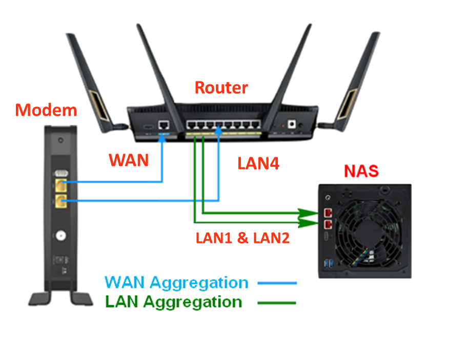
Например, сетевое хранилище (NAS) было подключено к маршрутизатору с помощью одного физического канала, но есть два компьютера, которые хотят получить доступ к информации NAS одновременно, что будет ограничено пропускной способностью 1 Гбит/с кабеля Ethernet. Другими словами, ограничение пропускной способности для двух компьютеров составляет 500 Мбит/с.
Однако после включения Link Aggregation (LACP) для объединения маршрутизатора и NAS по двум физическим каналам ограничение максимальной пропускной способности каждого компьютера станет 1 Гбит/с.
Примечание 1. Пропускная способность в приведенном выше примере является теоретическим значением. Обратите внимание, что фактическая величина будет зависеть от сценария использования.
Примечание 2. Устройства, которые хотят использовать функцию Link Aggregation (LACP), должны поддерживать протокол IEEE 802.3ad. Например, если Вы хотите использовать маршрутизатор и NAS для агрегации каналов (LACP), то оба они должны поддерживать IEEE 802.3ad.
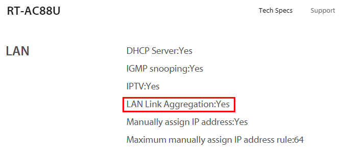
Пожалуйста, обратитесь к странице модели продукта на официальном сайте ASUS, чтобы проверить, поддерживает ли Ваш маршрутизатор ASUS Link Aggregation (LACP). У разных моделей могут быть разные спецификации.
Вы можете обратиться к Часто задаваемым вопросам
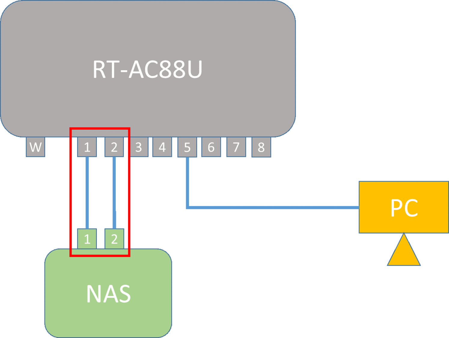
В следующих шагах в качестве примера показано подключение NAS к RT-AC88U:
1. Используйте кабель Ethernet для подключения к порту LAN 1 NAS между портом LAN 1 RT-AC88U. Затем с помощью другого кабеля Ethernet подключитесь к порту LAN 2 NAS между портом LAN 2 RT-AC88U.
См. Следующий рисунок:
2. Подключите компьютер к маршрутизатору через проводное или Wi-Fi соединение и введите IP-адрес локальной сети маршрутизатора или URL-адрес маршрутизатора http://www.asusrouter.com в веб-интерфейсе.

Пожалуйста, обратитесь по ссылке для ознакомления: Как войти на страницу настроек роутера (веб-интерфейс) (ASUSWRT)?
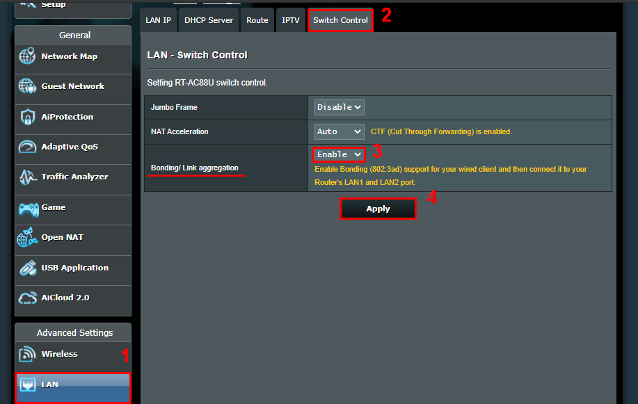
3. После входа выберите [LAN] > [Switch Control] > [Bonding / Link aggregation] и выберите [Включить] >[Применить]
Примечание: Если Вы забыли имя пользователя и/или пароль, восстановите маршрутизатор до заводского состояния по умолчанию.
Пожалуйста, воспользуйтесь ссылкой: Как сбросить роутер до заводских настроек?
4. Войдите на страницу настроек NAS, включите функцию Link Aggregation (LACP) NAS.
I. Включить агрегацию рекламных ссылок 802.3 (LACP)
II. Убедитесь, что функция включена на странице настроек NAS.
III. Готово.
Примечание: Если у Вас возникнут вопросы по NAS, обратитесь к производителю устройства.
5. Завершите настройку агрегирования ссылок (LACP).
Часто задаваемые вопросы
1. Почему у меня в устройствах нет функции Link Aggregation (LACP)?
Только если устройства поддерживают IEEE 802.3ad, тогда можно использовать функцию Link Aggregation. Пожалуйста, проверьте страницу спецификаций вашего устройства, если оно поддерживает эту функцию, или обратитесь к производителю.
Маршрутизаторы ASUS могут проверить функцию на странице спецификаций официального сайта продукта.
Возьмем, к примеру, RT-AC88U:
https://www.asus.com/Networking-IoT-Servers/Whole-Home-Mesh-WiFi-System/All-series/RT-AC88U/techspec/
2. Могу ли я включить 2 пары Link Aggregation (LACP)?
Нет, маршрутизаторы ASUS поддерживают использование только 1-парной агрегации каналов (LACP).
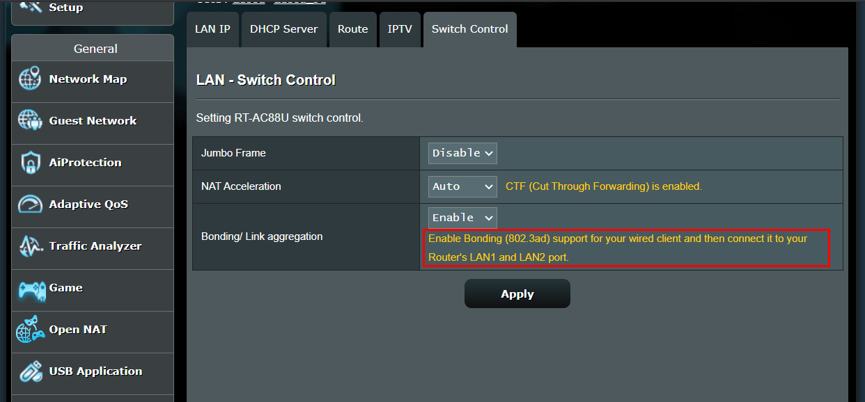
После включения функции на странице настроек появится всплывающее окно, в котором объясняются 2 порта LAN, которые маршрутизатор поддерживает с помощью Link Aggregation (LACP), а затем Вы можете следовать инструкциям на странице, чтобы подключиться к соответствующим портам LAN. .
См. Следующий рисунок:
Включите поддержку соединения (802.3ad) для проводного клиента, а затем подключите его к портам LAN 1 и LAN 2 Вашего маршрутизатора.
3. Если я устанавливаю систему AiMesh уже в моем доме и включаю Link Aggregation (LACP) в маршрутизаторе AiMesh, возможно ли, чтобы узел AiMesh также синхронизировал включенную функцию?
Нет. Link Aggregation (LACP) теперь может работать только в маршрутизаторе AiMesh, узлы AiMesh не поддерживают.
Примечание: Дополнение к определениям.
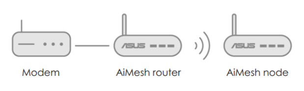
Маршрутизатор AiMesh: первый маршрутизатор, который подключается к модему напрямую.
Узел AiMesh: другие маршрутизаторы, которые подключаются к маршрутизатору AiMesh.
Для получения более подробной информации о системе AiMesh, пожалуйста, обратитесь к статье: https://www.asus.com/microsite/aimesh/en/index.html
4. Включено ли агрегирование каналов по умолчанию в режиме AP?
Если маршрутизатор находится в режиме AP, необходимо настроить агрегацию каналов на основном маршрутизаторе.
В режиме AP маршрутизатор подключается к беспроводному маршрутизатору через кабель Ethernet, чтобы расширить зону покрытия беспроводного сигнала для других сетевых клиентов. В этом режиме функции межсетевого экрана, совместного использования IP-адреса и NAT по умолчанию отключены.
Для получения дополнительных сведений о режиме AP см.: [Беспроводное устройство] Как настроить режим точки доступа (AP) на маршрутизаторе ASUS?
5. В чем разница между агрегацией WAN и агрегацией LAN?
Агрегация WAN: может увеличить скорость передачи данных между модемом интернет-провайдера и Вашим маршрутизатором. Агрегация локальной сети: может увеличить скорость передачи данных между Вашим маршрутизатором и устройствами, подключенными к маршрутизатору, такими как NAS или компьютер с двумя портами Ethernet.
Например, если все устройства Вашей сетевой среде поддерживают IEEE 802.3ad и агрегацию WAN/агрегацию LAN и поддерживают полосу пропускания 2G WAN, если Вы хотите увеличить скорость передачи данных между маршрутизатором и NAS, Вы можете настроить агрегацию локальной сети. Если Вы хотите увеличить скорость передачи данных между модемом интернет-провайдера и вашим маршрутизатором, Вы можете настроить агрегацию WAN. Если Вы хотите увеличить скорость передачи данных от модема интернет-провайдера к NAS, включите агрегацию WAN и агрегацию LAN, чтобы получить скорость передачи 2G.
Как настроить WAN Агрегацию в роутерах ASUS [WAN] Как включить агрегацию портов в роутере ASUS?
Как получить (Утилиты / Прошивку)?
Вы можете загрузить последние версии драйверов, программного обеспечения, встроенного ПО и руководств пользователя через Центр загрузки ASUS.
Если Вам нужна дополнительная информация о Центре загрузки ASUS, пожалуйста, перейдите по ссылке.
[Wireless Router] How to setup link aggregation on ASUS router?(Teaming Port/LACP)
Link Aggregation Control Protocol (LACP) is part of IEEE 802.3ad protocol, and you may combine 2 Ethernet links into one single logical link with 2 network devices. Also, you could find following benefits when enabling Link Aggregation (LACP) in ASUS routers.
- When one of the connection is failed, you still have another one to keep the connection to the internet.
- Increased bandwidth improves the transmission speed between your devices.
For example, the Network attached storage (NAS) was connected to the router by one physical link, but there are two computers want to access the information of the NAS in the same time, which would be limited by the 1Gbps bandwidth of the Ethernet cable. Therefore, in other words, the bandwidth limitation for the two computers is 500Mbps.
However, after enabling Link Aggregation (LACP) to combine the router and the NAS by two physical links, and the max bandwidth limitation of each computer will turn to 1Gbps.
Notice 1: The bandwidth in above example is theoretical value. Please be notified that actual value will depend on the usage scenario.
Notice 2: The devices that want to use Link Aggregation (LACP) function need to support IEEE 802.3ad protocol in the meantime. For example, if you want to use the router and the NAS to do the Link Aggregation (LACP), and both of them need to support IEEE 802.3ad.
Please refer to the Product model page in ASUS official site for checking if your ASUS router supports Link Aggregation (LACP). Different models might have different spec.
In addition, you could refer to FAQ 1 to check.
Following steps take NAS connect to RT-AC88U as an example:
1. Please use the Ethernet cable to connect to LAN 1 Port of the NAS between LAN 1 Port of RT-AC88U. And then use another Ethernet cable to connect to LAN 2 Port of the NAS between LAN 2 Port of RT-AC88U.
Refer to following pic:
2. Connect your computer to the router via wired or WiFi connection and enter your router LAN IP or router URL http://www.asusrouter.com to the WEB GUI.

Please refer to How to enter the router setting page(Web GUI) to learn more.
3. After login, Click [LAN] > [Switch Control] > [Bonding / Link aggregation] choose [Enable] >[Apply]
Notice: If you forgot the user name and/or password, please restore the router to the factory default status.
Please refer to How to reset the router to factory default setting? to learn more.
4. Enter the setting page of NAS, enable the Link Aggregation(LACP) feature of NAS.
i. Enable 802.3 ad Link Aggregation (LACP)
ii. Check the function is enabled in the setting page of NAS
iii. Finished.
Notice: If there’s any question about the NAS, please ask the device manufacturer.
5. Finish Link Aggregation (LACP) settings.
FAQ
1. Why couldn’t I find the Link Aggregation (LACP) options in my devices?
Only if the devices support IEEE 802.3ad then could use Link Aggregation function. Please check the spec page of your device if the device support this function or ask the manufacturer.
ASUS Routers could check the function from the Specification Page of Product official site.
Take RT-AC88U as an example:
https://www.asus.com/
2. Is that possible for me to enable 2 pairs of Link aggregation (LACP)?
No, ASUS routers only support to use 1 pair Link Aggregation (LACP).
After enable the function, there’ll be a pop-out window in setting page explains the 2 LAN ports that the router supports with Link Aggregation (LACP), and then you could follow the instructions on the page to connect to the corresponded LAN ports.
Refer to following pic:
Enable Bonding (802.3ad) support for your wired client and then connect it to your Router’s LAN 1 and LAN 2 port.
3. If I setup the AiMesh system already in my house, and enable the Link Aggregation (LACP) in the AiMesh router, is that possible for the AiMesh node also sync the function which is being enabled?
No. Link Aggregation (LACP) now only could be worked in AiMesh router, AiMesh nodes don’t support.
Note: Definition supplement
AiMesh router: The first router that connects to the modem directly.
AiMesh node: Other routers which connect to the AiMesh router.
For more details of AiMesh System, please refer to : https://www.asus.com/microsite/aimesh/en/index.html
4. Is link aggregation enabled by default in AP mode?
If the router under AP mode, the link aggregation should adjust in ther main router.
In AP mode, router connects to a wireless router through an Ethernet cable to extend the coverage of wireless signal to other network clients. In this mode, the firewall, IP sharing, and NAT functions are disabled by default.
For more details about AP mode, please refer to : [Wireless Router] How to set up operation mode- Access Point(AP) mode?
5. What is the difference between WAN Aggregation and LAN Aggregation?
WAN Aggregation: it can increase the transfer speed between ISP modem and your router.
LAN Aggregation: It can increase the transfer speed between your router to the devices connect to router, like NAS or a computer with two Ethernet ports.
For example, if all devices in your network environment all support IEEE 802.3ad and WAN aggregation/LAN aggregation and support 2G WAN bandwidth,
If you wish to increase the transfer speed between router and NAS, you can set up LAN aggregation.
If you wish to increase the transfer speed between ISP modem and your router, you can set up WAN aggregation.
If you wish to increase the transfer speed from ISP modem to NAS, please enable both WAN aggregation and LAN aggregation to get 2G transfer speed.
For how to set up WAN Aggregation in ASUS router, please refer to [WAN] How to enable WAN Aggregation on ASUS Router?
How to get the (Utility / Firmware)?
You can download the latest drivers, software, firmware and user manuals in the ASUS Download Center.
If you need more information about the ASUS Download Center, please refer this link.
[Wireless Router] How to setup link aggregation on ASUS router?(Teaming Port/LACP)
Link Aggregation Control Protocol (LACP) is part of IEEE 802.3ad protocol, and you may combine 2 Ethernet links into one single logical link with 2 network devices. Also, you could find following benefits when enabling Link Aggregation (LACP) in ASUS routers.
- When one of the connection is failed, you still have another one to keep the connection to the internet.
- Increased bandwidth improves the transmission speed between your devices.
For example, the Network attached storage (NAS) was connected to the router by one physical link, but there are two computers want to access the information of the NAS in the same time, which would be limited by the 1Gbps bandwidth of the Ethernet cable. Therefore, in other words, the bandwidth limitation for the two computers is 500Mbps.
However, after enabling Link Aggregation (LACP) to combine the router and the NAS by two physical links, and the max bandwidth limitation of each computer will turn to 1Gbps.
Notice 1: The bandwidth in above example is theoretical value. Please be notified that actual value will depend on the usage scenario.
Notice 2: The devices that want to use Link Aggregation (LACP) function need to support IEEE 802.3ad protocol in the meantime. For example, if you want to use the router and the NAS to do the Link Aggregation (LACP), and both of them need to support IEEE 802.3ad.
Please refer to the Product model page in ASUS official site for checking if your ASUS router supports Link Aggregation (LACP). Different models might have different spec.
In addition, you could refer to FAQ 1 to check.
Following steps take NAS connect to RT-AC88U as an example:
1. Please use the Ethernet cable to connect to LAN 1 Port of the NAS between LAN 1 Port of RT-AC88U. And then use another Ethernet cable to connect to LAN 2 Port of the NAS between LAN 2 Port of RT-AC88U.
Refer to following pic:
2. Connect your computer to the router via wired or WiFi connection and enter your router LAN IP or router URL http://www.asusrouter.com to the WEB GUI.
Please refer to How to enter the router setting page(Web GUI) to learn more.
3. After login, Click [LAN] > [Switch Control] > [Bonding / Link aggregation] choose [Enable] >[Apply]
Notice: If you forgot the user name and/or password, please restore the router to the factory default status.
Please refer to How to reset the router to factory default setting? to learn more.
4. Enter the setting page of NAS, enable the Link Aggregation(LACP) feature of NAS.
i. Enable 802.3 ad Link Aggregation (LACP)
ii. Check the function is enabled in the setting page of NAS
iii. Finished.
Notice: If there’s any question about the NAS, please ask the device manufacturer.
5. Finish Link Aggregation (LACP) settings.
FAQ
1. Why couldn’t I find the Link Aggregation (LACP) options in my devices?
Only if the devices support IEEE 802.3ad then could use Link Aggregation function. Please check the spec page of your device if the device support this function or ask the manufacturer.
ASUS Routers could check the function from the Specification Page of Product official site.
Take RT-AC88U as an example:
https://www.asus.com/
2. Is that possible for me to enable 2 pairs of Link aggregation (LACP)?
No, ASUS routers only support to use 1 pair Link Aggregation (LACP).
After enable the function, there’ll be a pop-out window in setting page explains the 2 LAN ports that the router supports with Link Aggregation (LACP), and then you could follow the instructions on the page to connect to the corresponded LAN ports.
Refer to following pic:
Enable Bonding (802.3ad) support for your wired client and then connect it to your Router’s LAN 1 and LAN 2 port.
3. If I setup the AiMesh system already in my house, and enable the Link Aggregation (LACP) in the AiMesh router, is that possible for the AiMesh node also sync the function which is being enabled?
No. Link Aggregation (LACP) now only could be worked in AiMesh router, AiMesh nodes don’t support.
Note: Definition supplement
AiMesh router: The first router that connects to the modem directly.
AiMesh node: Other routers which connect to the AiMesh router.
For more details of AiMesh System, please refer to : https://www.asus.com/microsite/aimesh/en/index.html
4. Is link aggregation enabled by default in AP mode?
If the router under AP mode, the link aggregation should adjust in ther main router.
In AP mode, router connects to a wireless router through an Ethernet cable to extend the coverage of wireless signal to other network clients. In this mode, the firewall, IP sharing, and NAT functions are disabled by default.
For more details about AP mode, please refer to : [Wireless Router] How to set up operation mode- Access Point(AP) mode?
5. What is the difference between WAN Aggregation and LAN Aggregation?
WAN Aggregation: it can increase the transfer speed between ISP modem and your router.
LAN Aggregation: It can increase the transfer speed between your router to the devices connect to router, like NAS or a computer with two Ethernet ports.
For example, if all devices in your network environment all support IEEE 802.3ad and WAN aggregation/LAN aggregation and support 2G WAN bandwidth,
If you wish to increase the transfer speed between router and NAS, you can set up LAN aggregation.
If you wish to increase the transfer speed between ISP modem and your router, you can set up WAN aggregation.
If you wish to increase the transfer speed from ISP modem to NAS, please enable both WAN aggregation and LAN aggregation to get 2G transfer speed.
For how to set up WAN Aggregation in ASUS router, please refer to [WAN] How to enable WAN Aggregation on ASUS Router?
How to get the (Utility / Firmware)?
You can download the latest drivers, software, firmware and user manuals in the ASUS Download Center.
If you need more information about the ASUS Download Center, please refer this link.

Похожие видео
Режим Dual WAN на роутерах ASUS — что с ним не так?Скачать

Wi-Fi 6 ТОП РОУТЕР Asus ROG Rapture GT-AX6000 на 2.5 гигабита с игровыми функциями и фишками NASСкачать

Двухдиапазонный Wi‑Fi роутер AX6000 с портом WAN/LAN 2,5 Гбит/с и поддержкой Mesh ӏ Archer AX80Скачать

РОУТЕР ASUS RT-AX55 С WI-FI 6 — БЮДЖЕТНЫЙ, НО МОЩНЫЙ РОУТЕР С КЛАССНЫМ ДИЗАЙНОМСкачать

МЕГА РОУТЕР ASUS RT-AX89X WI-FI 6, НА 10 ГИГАБИТ, SFP+ ДЛЯ ОПТИКИ, ФУНКЦИЯМИ NAS СЕРВЕРА И MESHСкачать

Главные преимущества роутера Asus RT AC58UСкачать

Дополнительные материалы
Настройка интернета от ТТК для Wi-Fi роутера на примере Asus RT N12 за 5 минутСкачать

Ремонт ноутбука DNS. Не включается. Ищем КЗСкачать

ПРОВЕЛИ 10 ГИГАБИТ ИНТЕРНЕТ В СТУДИЮ TECHNOZON. ТЕСТЫ РОУТЕРОВ ПО НОВОМУ! ОБЗОР СТУДИИ TECHNOZONСкачать
How to Setup Dual Wan on Asus Router for Internet FailoverСкачать

Новая технология Wi-Fi 6 (802.11ax): Как это работает на примере AiMesh системы ASUS (и не только)Скачать

✅ Обзор Asus RT AX3000 🔥 Лучший WiFi роутер для игр 2023 с Алиэкспресс — Какой роутер купить?Скачать

ASUS RT-AX82U, RT-AX86U и ZenWiFi AX Mini: блиц-обзор нового поколения роутеров с Wi-Fi 6Скачать

РОУТЕР ASUS RT-AC1200( обзор)Скачать

Роутеры на гигабит | Лучшие гигабитные роутеры для дома!Скачать

WIFI 6 РОУТЕР ASUS RT-AX53U ИЛИ БЮДЖЕТНЫЙ 802.11AX В ЛИНЕЙКЕ ИМЕНИТОГО БРЕНДАСкачать

РОУТЕР TP-LINK Archer AX73 C WI-FI 6. НАРОДНЫЙ ГИГАБИТ! AX5400Скачать

Как настроить и подключить Wi Fi роутер ASUS? (на примере ASUS RT-N16)Скачать

Как сделать mesh-систему из роутеров ASUS: пробуем AiMesh в делеСкачать

Deleted member 28123
Guest
-
#1
Hello everyone —
I managed to get link aggregation working with the 68u router model and wanted to share my method in this how-to guide.
Environment
— Router Model: AC68U using ports 3 & 4
— Firmware: Asuswrt-Merlin 376.47 with JFFS enabed
— Switch: Netgear GSM7224R (including other 802.3ad capable switches)
— User Scripts (in /jffs/scripts/): firewall-start and services-start
Inspiration & Credits
— LinkAgg script by @KAD — http://forums.smallnetbuilder.com/showthread.php?t=12735
— DD-WRT forum post by @mrengles — http://www.dd-wrt.com/phpBB2/viewtopic.php?p=869756
Description
After several attempts (and many failures) to get link aggregation working using the LinkAgg script, I decided to further investigate the underlining cause for the failures and concluded:
1. LinkAgg, which has bugs, was designed to work with the 66u model which uses different internal switch port mappings (this was mentioned in several posts)
2. For some reason, Vlan 3 does not appear to work properly in the 68u model. This meant that I needed to use vlan 4 and vlan 5 instead.
3. The use of the xmit_hash_policy option and the corresponding switch/NAS hashing option was needed in order for link aggregation to work with a variety of switches
& NAS boxes
*new edit.
4. A simpler method was required to get link aggregation working across reboots and firmware updates.
Enough said — let’s get to it
First & Foremost — Backup your current nvram via the ‘Administration — Restore/Save/Upload Setting’ tab or nvram+jffs using @john9527 nvram save/restore utility @ http://smallnetbuilderforums.com/threads/user-nvram-save-restore-utility-r21.19521/
Step 1 — NVRAM Edits |
Note: You will need to repeat this step if you clear the nvram ie. Beta to Final versions, resetting to Factory default
Apply the following changes to the router’s nvram:
Code:
nvram set vlan4ports="3 5t"
nvram set vlan5ports="4 5t"
nvram set vlan4hwname=et0
nvram set vlan5hwname=et0
nvram commit
Step 2 — Create/Edit services-start script
Include the following code in services-start script located in /jffs/scripts/ (you will need to create this file from scratch, if you haven’t done so already, with the right permissions)
Code:
#!/bin/sh

# Logger Services
logger -t "($(basename $0))" $$ SERVICES-START being started....

logger -t "($(basename $0))" $$ Bonding ports 3 and 4 commencing....
# Pre-Bonding
robocfg vlan 1 ports "1 2 5*"

# Bonding
sleep 2s
modprobe bonding
# Setting mode to 802.3ad
echo 802.3ad > /sys/class/net/bond0/bonding/mode
# Setting LACP rate to fast
echo fast > /sys/class/net/bond0/bonding/lacp_rate
# Setting MII monitoring interval to 50
echo 50 > /sys/class/net/bond0/bonding/miimon
# Setting xmit hash policy to layer3+4
echo 1 > /sys/class/net/bond0/bonding/xmit_hash_policy
ip link set bond0 up
echo +vlan4 > /sys/class/net/bond0/bonding/slaves
echo +vlan5 > /sys/class/net/bond0/bonding/slaves
brctl addif br0 bond0

# Post-Bonding
sleep 2s
logger -t "($(basename $0))" $$ Bonding Status....
cat /proc/net/bonding/bond0 | sed 's/^/+++  /' | logger
Step 3 — Create/Edit firewall-start script
Include the following code in firewall-start script located in /jffs/scripts/ (you will need to create this file from scratch, if you haven’t done so already, with the right permissions)
Code:
#!/bin/sh

# Bonding IPtables rules
iptables -I INPUT -i vlan4 -j ACCEPT
iptables -I INPUT -i vlan5 -j ACCEPT
iptables -I INPUT -i bond0 -j ACCEPT

# Firewall/IPtables Performance Tweak for Bond0 to be placed right after the above bonding rules and before your custom rules - if any.
iptables -D INPUT `iptables --line-numbers -nL INPUT | grep ESTABLISHED | tail -n1 | awk '{print $1}'`
iptables -I INPUT -m state --state RELATED,ESTABLISHED -j ACCEPT
Step 4 — Set the switch’s LAG hashing mode
This is the LAG config for the 2 switch ports you have connected to the router’s port 3 and 4.
— Set the hashing mode to «Source/Destination MAC, VLAN, EtherType, source MODID/port» or the equivalent mode in your switch.
Step 5 — Reboot
You should now have link aggregation working with your 68u router and 802.3ad capable switch
Last edited by a moderator:
-
#2
This looks pretty clean. You should consider creating a Wiki entry for it.
I’ll move your post to the Asuswrt-Merlin forum however, as this wouldn’t work with stock firmware (no user scripts).
Deleted member 28123
Guest
-
#3
Thanks. I will post the wiki entry later today..
I am sure this method would work for 68u routers loaded with tomato/dd-wrt firmware with some minor edits to this guide, specifically NVRAM edits and scripts, which is why I posted it under ASUS Wireless/AC section of the forum.
-
#4
How to: Enable root directory listing, rw rights?
Hi everyone,
I have just flashed my RT-N16 to the latest stable version (376.47).
Using Tomato Shibby earlier it was easy to config which directories of the router can be seen over FTP, even to give write permissions to them.
Now having this Merlin build -which is an absolute great custom firmware to my router — I have no idea what to do in order to have the router’s root directories listed on an FTP client? How to give write permission to a given directory of the router?
Can anybody help me on this issue?
(Sorry if this is not the right thread for this issue, I just could not find any other suitable)
Last edited:
-
#5
Thanks. I will post the wiki entry later today..
I am sure this method would work for 68u routers loaded with tomato/dd-wrt firmware with some minor edits to this guide, specifically NVRAM edits and scripts, which is why I posted it under ASUS Wireless/AC section of the forum.
I’m not sure if Tomato has the bonding.ko kernel module included.
Deleted member 28123
Guest
-
#6
You are right. It was available on older versions of tomatousb but not anymore.
I updated the wiki entry for link aggregation on github and cleaned up the page a bit.
Last edited by a moderator:
-
#7
Thanks a lot!
But one more thing…
If I plug another cable in port 1 or 2 it seems that I’m unable to access the device from the wireless connection…
And if I reboot the router with only the port 3 and 4 connected it’s working…
Any idea way?
tino
New Around Here
-
#8
Hello
I’ve tried it with following environment:
— Router Model: AC87U using ports 3 & 4 (Physical LAN Port 1 & 2)
— Firmware: Asuswrt-Merlin 376.49_4 with JFFS enabed
— Counterpart: Synology DS412+ (DSM 5.1-5021 Update 2)
This is the original configuration of the Router.
Code:
boss@RT-AC87U:/# robocfg show
Switch: enabled
Port 0: 1000FD enabled stp: none vlan: 2 jumbo: off mac: 00:0b:00:00:ad:d0
Port 1:   DOWN enabled stp: none vlan: 1 jumbo: off mac: 00:00:00:00:00:00
Port 2:   DOWN enabled stp: none vlan: 1 jumbo: off mac: 00:00:00:00:00:00
Port 3: 1000FD enabled stp: none vlan: 1 jumbo: off mac: 00:11:32:25:0d:78
Port 4:   DOWN enabled stp: none vlan: 1 jumbo: off mac: 00:00:00:00:00:00
Port 8: 1000FD enabled stp: none vlan: 1 jumbo: off mac: 54:a0:50:e5:1e:f8
VLANs: BCM5301x enabled mac_check mac_hash
   1: vlan1: 1 2 3 5 8t
   2: vlan2: 0 8t
1045: vlan1045: 4 7t
1046: vlan1046: 0 5 8t
1047: vlan1047: 1 3 5 8t
1099: vlan1099: 1t 2 4t 8u
1100: vlan1100: 0 2t 3 4 8u
1101: vlan1101: 0t 2 4 7t
1102: vlan1102: 0 3t 7 8t
1103: vlan1103: 0 3 7t 8u


boss@RT-AC87U:/# brctl show
bridge name	bridge id		STP enabled	interfaces
br0		8000.54a050e51ef8	yes		vlan1
							eth1
boss@RT-AC87U:/# cat /proc/net/vlan/config
VLAN Dev name	 | VLAN ID
Name-Type: VLAN_NAME_TYPE_PLUS_VID_NO_PAD
vlan1          | 1  | eth0
vlan2          | 2  | eth0

boss@RT-AC87U:/# ifconfig | grep Link
br0        Link encap:Ethernet  HWaddr 54:A0:50:E5:1E:F8
br0:0      Link encap:Ethernet  HWaddr 54:A0:50:E5:1E:F8
eth0       Link encap:Ethernet  HWaddr 54:A0:50:E5:1E:F8
eth1       Link encap:Ethernet  HWaddr 54:A0:50:E5:1E:F8
lo         Link encap:Local Loopback
vlan1      Link encap:Ethernet  HWaddr 54:A0:50:E5:1E:F8
vlan2      Link encap:Ethernet  HWaddr 54:A0:50:E5:1E:F8

boss@RT-AC87U:/# nvram show | sort | grep vlan
size: 42392 bytes (23144 left)
lan_ifnames=vlan1 eth1 wifi0
landevs=vlan1 wl0
vlan1hwname=et1
vlan1ports=1 2 3 5 7*
vlan2hwname=et1
vlan2ports=0 7
wan0_gw_ifname=vlan2
wan0_ifname=vlan2
wan_ifnames=vlan2
wandevs=vlan2
wl0_vlan_prio_mode=off
wl1_vlan_prio_mode=off
wl_vlan_prio_mode=off
The both Cables from the DiskStation are connected to physical Port 1 & 2 which are mapped to port 3 & 5. For any reason the roboctl command doesn’t show the «Port 4» correctly…
based on your tutorial and the original configuration I’ve tried it manually with following commands (the LinkAgg script was not working). I’ve added the commands to create the vlans otherwise it fails to add the (not existing) vlan to the bond0.
Code:
boss@RT-AC87U:/# nvram set vlan103ports="3 8t"
boss@RT-AC87U:/# nvram set vlan104ports="5 8t"
boss@RT-AC87U:/# nvram set vlan103hwname=et0
boss@RT-AC87U:/# nvram set vlan104hwname=et0
boss@RT-AC87U:/# nvram commit

boss@RT-AC87U:/# robocfg vlan 1 ports "1 2 8t"
boss@RT-AC87U:/# modprobe bonding
boss@RT-AC87U:/# echo 802.3ad > /sys/class/net/bond0/bonding/mode
boss@RT-AC87U:/# echo fast > /sys/class/net/bond0/bonding/lacp_rate
boss@RT-AC87U:/# echo 100 > /sys/class/net/bond0/bonding/miimon
boss@RT-AC87U:/# echo 1 > /sys/class/net/bond0/bonding/xmit_hash_policy
boss@RT-AC87U:/# ip link set bond0 up
boss@RT-AC87U:/# echo +vlan103 > /sys/class/net/bond0/bonding/slaves
echo: write error: No such device
boss@RT-AC87U:/# vconfig add eth0 103
boss@RT-AC87U:/# echo +vlan103 > /sys/class/net/bond0/bonding/slaves
boss@RT-AC87U:/# echo +vlan104 > /sys/class/net/bond0/bonding/slaves
echo: write error: No such device
boss@RT-AC87U:/# vconfig add eth0 104
boss@RT-AC87U:/# echo +vlan104 > /sys/class/net/bond0/bonding/slaves
boss@RT-AC87U:/# brctl addif br0 bond0

boss@RT-AC87U:/# iptables -I INPUT 1 -i vlan103 -j ACCEPT
boss@RT-AC87U:/# iptables -I INPUT 1 -i vlan104 -j ACCEPT
boss@RT-AC87U:/# iptables -I INPUT 1 -i bond0 -j ACCEPT
the new configuration is the following:
Code:
boss@RT-AC87U:/# robocfg show
Switch: enabled
Port 0: 1000FD enabled stp: none vlan: 2 jumbo: off mac: 00:0b:00:00:ad:d0
Port 1:   DOWN enabled stp: none vlan: 1 jumbo: off mac: 00:00:00:00:00:00
Port 2:   DOWN enabled stp: none vlan: 1 jumbo: off mac: 00:00:00:00:00:00
Port 3: 1000FD enabled stp: none vlan: 1 jumbo: off mac: 00:11:32:25:0d:78
Port 4:   DOWN enabled stp: none vlan: 1 jumbo: off mac: 00:00:00:00:00:00
Port 8: 1000FD enabled stp: none vlan: 1 jumbo: off mac: 00:11:32:25:0d:77
VLANs: BCM5301x enabled mac_check mac_hash
   1: vlan1: 1 2 8t
   2: vlan2: 0 8t
1045: vlan1045: 4 7t
1046: vlan1046: 0 5 8t
1047: vlan1047: 1 3 5 8t
1099: vlan1099: 1t 2 4t 8u
1100: vlan1100: 0 2t 3 4 8u
1101: vlan1101: 0t 2 4 7t
1102: vlan1102: 0 3t 7 8t
1103: vlan1103: 0 3 7t 8u

boss@RT-AC87U:/# brctl show
bridge name	bridge id		STP enabled	interfaces
br0		8000.54a050e51ef8	yes		vlan1
							eth1
							bond0

boss@RT-AC87U:/# cat /proc/net/vlan/config
VLAN Dev name	 | VLAN ID
Name-Type: VLAN_NAME_TYPE_PLUS_VID_NO_PAD
vlan1          | 1  | eth0
vlan2          | 2  | eth0
vlan103        | 103  | eth0
vlan104        | 104  | eth0

boss@RT-AC87U:/# ifconfig | grep Link
bond0      Link encap:Ethernet  HWaddr 54:A0:50:E5:1E:F8
br0        Link encap:Ethernet  HWaddr 54:A0:50:E5:1E:F8
br0:0      Link encap:Ethernet  HWaddr 54:A0:50:E5:1E:F8
eth0       Link encap:Ethernet  HWaddr 54:A0:50:E5:1E:F8
eth1       Link encap:Ethernet  HWaddr 54:A0:50:E5:1E:F8
lo         Link encap:Local Loopback
vlan1      Link encap:Ethernet  HWaddr 54:A0:50:E5:1E:F8
vlan103    Link encap:Ethernet  HWaddr 54:A0:50:E5:1E:F8
vlan104    Link encap:Ethernet  HWaddr 54:A0:50:E5:1E:F8
vlan2      Link encap:Ethernet  HWaddr 54:A0:50:E5:1E:F8

boss@RT-AC87U:/# nvram show | sort | grep vlan
size: 42464 bytes (23072 left)
lan_ifnames=vlan1 eth1 wifi0
landevs=vlan1 wl0
vlan103hwname=et0
vlan103ports=3 8t
vlan104hwname=et0
vlan104ports=5 8t
vlan1hwname=et1
vlan1ports=1 2 3 5 7*
vlan2hwname=et1
vlan2ports=0 7
wan0_gw_ifname=vlan2
wan0_ifname=vlan2
wan_ifnames=vlan2
wandevs=vlan2
wl0_vlan_prio_mode=off
wl1_vlan_prio_mode=off
wl_vlan_prio_mode=off

boss@RT-AC87U:/# cat /proc/net/bonding/bond0
Ethernet Channel Bonding Driver: v3.7.0 (June 2, 2010)

Bonding Mode: IEEE 802.3ad Dynamic link aggregation
Transmit Hash Policy: layer3+4 (1)
MII Status: up
MII Polling Interval (ms): 100
Up Delay (ms): 0
Down Delay (ms): 0

802.3ad info
LACP rate: fast
Aggregator selection policy (ad_select): stable
Active Aggregator Info:
	Aggregator ID: 1
	Number of ports: 1
	Actor Key: 5
	Partner Key: 1
	Partner Mac Address: 00:00:00:00:00:00

Slave Interface: vlan103
MII Status: up
Link Failure Count: 0
Permanent HW addr: 54:a0:50:e5:1e:f8
Aggregator ID: 1
Slave queue ID: 0

Slave Interface: vlan104
MII Status: up
Link Failure Count: 0
Permanent HW addr: 54:a0:50:e5:1e:f8
Aggregator ID: 2
Slave queue ID: 0
I’ve also tried to add the new vlans to the switch config, with following commands:
Code:
boss@RT-AC87U:/# robocfg vlan 103 ports "3 8t"
boss@RT-AC87U:/#robocfg vlan 104 ports "5u 8t"
boss@RT-AC87U:/# robocfg show
Switch: enabled
Port 0: 1000FD enabled stp: none vlan: 2 jumbo: off mac: 00:0b:00:00:ad:d0
Port 1:   DOWN enabled stp: none vlan: 1 jumbo: off mac: 00:00:00:00:00:00
Port 2:   DOWN enabled stp: none vlan: 1 jumbo: off mac: 00:00:00:00:00:00
Port 3: 1000FD enabled stp: none vlan: 103 jumbo: off mac: 00:11:32:25:0d:77
Port 4:   DOWN enabled stp: none vlan: 1 jumbo: off mac: 00:00:00:00:00:00
Port 8: 1000FD enabled stp: none vlan: 1 jumbo: off mac: 54:a0:50:e5:1e:f8
VLANs: BCM5301x enabled mac_check mac_hash
   1: vlan1: 1 2 8t
   2: vlan2: 0 8t
 103: vlan103: 3 8t
 104: vlan104: 5 8t
1045: vlan1045: 4 7t
1046: vlan1046: 0 5 8t
1047: vlan1047: 1 2 3 5 7t 8t
1099: vlan1099: 1t 2 4t 8u
1100: vlan1100: 3 4 8t
1101: vlan1101: 0t 2 4 7t
1102: vlan1102: 0 1 7
1103: vlan1103: 0 1t 3 7t 8u
Bus this was also not working
The bond configuration on the DiskStation:
Code:
DiskStation> cat /proc/net/bonding/bond0
Ethernet Channel Bonding Driver: v3.7.1 (April 27, 2011)

Bonding Mode: IEEE 802.3ad Dynamic link aggregation
Transmit Hash Policy: layer2 (0)
MII Status: up
MII Polling Interval (ms): 100
Up Delay (ms): 100
Down Delay (ms): 0

802.3ad info
LACP rate: fast
Min links: 0
Aggregator selection policy (ad_select): stable
Active Aggregator Info:
	Aggregator ID: 2
	Number of ports: 1
	Actor Key: 17
	Partner Key: 1
	Partner Mac Address: 00:00:00:00:00:00

Slave Interface: eth0
Speed: 1000
Duplex: full
MII Status: up
Speed: 1000 Mbps
Duplex: full
Link Failure Count: 2
Permanent HW addr: 00:11:32:25:0d:77
Aggregator ID: 1
Slave queue ID: 0

Slave Interface: eth1
Speed: 1000
Duplex: full
MII Status: up
Speed: 1000 Mbps
Duplex: full
Link Failure Count: 1
Permanent HW addr: 00:11:32:25:0d:78
Aggregator ID: 2
Slave queue ID: 0
DiskStation>
From my point of view the configuration looks okay. But the DiskStation is not reachable (e.g. ping IP) with this configuration. I couldn’t find and useful log-information. Thus I haven’t any Idea to proceed
Can you give me any hint? Please!!!
Kind Regards Tino
Deleted member 28123
Guest
-
#9
Can you give me any hint? Please!!!
There are a couple of issues with your config but let us first get some additional details —
what’s the output of ifconfig?
tino
New Around Here
-
#10
Oh, what a blame. I’m looking forward to know them
the original ifconfig (after reboot) is:
Code:
boss@RT-AC87U:/# ifconfig -a
aux0       Link encap:Ethernet  HWaddr 54:A0:50:E5:1E:F8
           BROADCAST MULTICAST  MTU:1500  Metric:1
           RX packets:250 errors:0 dropped:0 overruns:0 frame:0
           TX packets:0 errors:0 dropped:0 overruns:0 carrier:0
           collisions:0 txqueuelen:1000
           RX bytes:25213 (24.6 KiB)  TX bytes:0 (0.0 B)
           Interrupt:180 Base address:0x5000

br0        Link encap:Ethernet  HWaddr 54:A0:50:E5:1E:F8
           inet addr:10.1.60.1  Bcast:10.1.60.255  Mask:255.255.255.0
           UP BROADCAST RUNNING MULTICAST  MTU:1500  Metric:1
           RX packets:20743 errors:0 dropped:0 overruns:0 frame:0
           TX packets:20378 errors:0 dropped:0 overruns:0 carrier:0
           collisions:0 txqueuelen:0
           RX bytes:1669807 (1.5 MiB)  TX bytes:12968782 (12.3 MiB)

br0:0      Link encap:Ethernet  HWaddr 54:A0:50:E5:1E:F8
           inet addr:169.254.39.123  Bcast:169.254.39.255  Mask:255.255.255.0
           UP BROADCAST RUNNING MULTICAST  MTU:1500  Metric:1

eth0       Link encap:Ethernet  HWaddr 54:A0:50:E5:1E:F8
           UP BROADCAST RUNNING MULTICAST  MTU:1500  Metric:1
           RX packets:26183 errors:0 dropped:0 overruns:0 frame:0
           TX packets:21961 errors:0 dropped:0 overruns:0 carrier:0
           collisions:0 txqueuelen:1000
           RX bytes:7550971 (7.2 MiB)  TX bytes:7961272 (7.5 MiB)
           Interrupt:181 Base address:0x6000

eth1       Link encap:Ethernet  HWaddr 54:A0:50:E5:1E:F8
           UP BROADCAST RUNNING MULTICAST  MTU:1500  Metric:1
           RX packets:19560 errors:0 dropped:0 overruns:0 frame:2700
           TX packets:16946 errors:0 dropped:0 overruns:0 carrier:0
           collisions:0 txqueuelen:1000
           RX bytes:3675544 (3.5 MiB)  TX bytes:13781858 (13.1 MiB)
           Interrupt:163

lo         Link encap:Local Loopback
           inet addr:127.0.0.1  Mask:255.0.0.0
           UP LOOPBACK RUNNING MULTICAST  MTU:16436  Metric:1
           RX packets:145 errors:0 dropped:0 overruns:0 frame:0
           TX packets:145 errors:0 dropped:0 overruns:0 carrier:0
           collisions:0 txqueuelen:0
           RX bytes:17946 (17.5 KiB)  TX bytes:17946 (17.5 KiB)

vlan1      Link encap:Ethernet  HWaddr 54:A0:50:E5:1E:F8
           UP BROADCAST RUNNING MULTICAST  MTU:1500  Metric:1
           RX packets:9871 errors:0 dropped:0 overruns:0 frame:0
           TX packets:11105 errors:0 dropped:0 overruns:0 carrier:0
           collisions:0 txqueuelen:0
           RX bytes:563195 (549.9 KiB)  TX bytes:5300830 (5.0 MiB)

vlan2      Link encap:Ethernet  HWaddr 54:A0:50:E5:1E:F8
           inet addr:80.109.113.143  Bcast:80.109.113.255  Mask:255.255.255.0
           UP BROADCAST RUNNING MULTICAST  MTU:1500  Metric:1
           RX packets:8961 errors:0 dropped:0 overruns:0 frame:0
           TX packets:2483 errors:0 dropped:0 overruns:0 carrier:0
           collisions:0 txqueuelen:0
           RX bytes:1208752 (1.1 MiB)  TX bytes:318108 (310.6 KiB)
and after the configuration described above:
Code:
boss@RT-AC87U:/# ifconfig
bond0      Link encap:Ethernet  HWaddr 54:A0:50:E5:1E:F8
           UP BROADCAST RUNNING MASTER MULTICAST  MTU:1500  Metric:1
           RX packets:0 errors:0 dropped:0 overruns:0 frame:0
           TX packets:49 errors:0 dropped:0 overruns:0 carrier:0
           collisions:0 txqueuelen:0
           RX bytes:0 (0.0 B)  TX bytes:3632 (3.5 KiB)

br0        Link encap:Ethernet  HWaddr 54:A0:50:E5:1E:F8
           inet addr:10.1.60.1  Bcast:10.1.60.255  Mask:255.255.255.0
           UP BROADCAST RUNNING MULTICAST  MTU:1500  Metric:1
           RX packets:77262 errors:0 dropped:0 overruns:0 frame:0
           TX packets:58137 errors:0 dropped:0 overruns:0 carrier:0
           collisions:0 txqueuelen:0
           RX bytes:8990133 (8.5 MiB)  TX bytes:24832735 (23.6 MiB)

br0:0      Link encap:Ethernet  HWaddr 54:A0:50:E5:1E:F8
           inet addr:169.254.39.123  Bcast:169.254.39.255  Mask:255.255.255.0
           UP BROADCAST RUNNING MULTICAST  MTU:1500  Metric:1

eth0       Link encap:Ethernet  HWaddr 54:A0:50:E5:1E:F8
           UP BROADCAST RUNNING MULTICAST  MTU:1500  Metric:1
           RX packets:583347 errors:0 dropped:0 overruns:0 frame:0
           TX packets:226792 errors:0 dropped:0 overruns:0 carrier:0
           collisions:0 txqueuelen:1000
           RX bytes:231605713 (220.8 MiB)  TX bytes:42088122 (40.1 MiB)
           Interrupt:181 Base address:0x6000

eth1       Link encap:Ethernet  HWaddr 54:A0:50:E5:1E:F8
           UP BROADCAST RUNNING MULTICAST  MTU:1500  Metric:1
           RX packets:193286 errors:0 dropped:0 overruns:0 frame:280231
           TX packets:191623 errors:0 dropped:0 overruns:0 carrier:0
           collisions:0 txqueuelen:1000
           RX bytes:34326575 (32.7 MiB)  TX bytes:214267467 (204.3 MiB)
           Interrupt:163

lo         Link encap:Local Loopback
           inet addr:127.0.0.1  Mask:255.0.0.0
           UP LOOPBACK RUNNING MULTICAST  MTU:16436  Metric:1
           RX packets:2074 errors:0 dropped:0 overruns:0 frame:0
           TX packets:2074 errors:0 dropped:0 overruns:0 carrier:0
           collisions:0 txqueuelen:0
           RX bytes:254622 (248.6 KiB)  TX bytes:254622 (248.6 KiB)

vlan1      Link encap:Ethernet  HWaddr 54:A0:50:E5:1E:F8
           UP BROADCAST RUNNING MULTICAST  MTU:1500  Metric:1
           RX packets:35261 errors:0 dropped:0 overruns:0 frame:0
           TX packets:39368 errors:0 dropped:0 overruns:0 carrier:0
           collisions:0 txqueuelen:0
           RX bytes:2510544 (2.3 MiB)  TX bytes:9434104 (8.9 MiB)

vlan103    Link encap:Ethernet  HWaddr 54:A0:50:E5:1E:F8
           UP BROADCAST RUNNING SLAVE MULTICAST  MTU:1500  Metric:1
           RX packets:0 errors:0 dropped:0 overruns:0 frame:0
           TX packets:47 errors:0 dropped:0 overruns:0 carrier:0
           collisions:0 txqueuelen:0
           RX bytes:0 (0.0 B)  TX bytes:3376 (3.2 KiB)

vlan104    Link encap:Ethernet  HWaddr 54:A0:50:E5:1E:F8
           UP BROADCAST RUNNING SLAVE MULTICAST  MTU:1500  Metric:1
           RX packets:0 errors:0 dropped:0 overruns:0 frame:0
           TX packets:2 errors:0 dropped:0 overruns:0 carrier:0
           collisions:0 txqueuelen:0
           RX bytes:0 (0.0 B)  TX bytes:256 (256.0 B)

vlan2      Link encap:Ethernet  HWaddr 54:A0:50:E5:1E:F8
           inet addr:80.109.97.157  Bcast:80.109.97.255  Mask:255.255.255.0
           UP BROADCAST RUNNING MULTICAST  MTU:1500  Metric:1
           RX packets:390338 errors:0 dropped:0 overruns:0 frame:0
           TX packets:44761 errors:0 dropped:0 overruns:0 carrier:0
           collisions:0 txqueuelen:0
           RX bytes:31820688 (30.3 MiB)  TX bytes:6221196 (5.9 MiB)
Deleted member 28123
Guest
-
#11
I’m looking forward to know them
")
Looking at the interfaces assigned to your br0 bridge and to avoid a potential misconfiguration due to the strange port mappings with the 87u (which I don’t have), you will need to carry out the following changes:
Connect cable 1 and 2 to physical ports 1 and 2 of the router and bonding ports of your DiskStation
Code:
nvram set vlan103ports="1 8t"
nvram set vlan104ports="2 8t"
nvram set vlan103hwname=et1
nvram set vlan104hwname=et1
nvram commit
Code:
robocfg vlan 1 ports "3 5 8*"
modprobe bonding
echo 802.3ad > /sys/class/net/bond0/bonding/mode
echo fast > /sys/class/net/bond0/bonding/lacp_rate
echo 100 > /sys/class/net/bond0/bonding/miimon
echo 1 > /sys/class/net/bond0/bonding/xmit_hash_policy
ip link set bond0 up
echo +vlan103 > /sys/class/net/bond0/bonding/slaves
echo +vlan104 > /sys/class/net/bond0/bonding/slaves
brctl addif br0 bond0
— Retain your current iptables/bonding specific rules.
— Do not run ‘vconfig add eth0 103’ or ‘vconfig add eth0 104’..
— Reboot.
As for your DiskStation (which I also don’t have) — you will need to change the transmit hash policy from layer2 (0) to layer3+4 (1) by running:
Code:
echo 1 > /sys/class/net/bond0/bonding/xmit_hash_policyNote: The above relative path may not be the correct path to your xmit_hash_policy file on your NAS. If this is the case, then search for that file, amend the relative path and apply. This change needs to be applied every time you reboot your NAS so make sure to add it to your start-up script/s.
The above approach/solution should work. Also, please include the output of ifconfig, robocfg show, nvram show | grep vlan, cat /proc/net/bonding/bond0 and remove any references to your public ip.
Last edited by a moderator:
tino
New Around Here
-
#12
Thanks a lot for your response!
It fails when I try to add the vlans to the bonding/slaves.
Code:
boss@RT-AC87U:/tmp/home/root# echo +vlan103 > /sys/class/net/bond0/bonding/slaves
echo: write error: No such device
boss@RT-AC87U:/tmp/home/root# echo +vlan104 > /sys/class/net/bond0/bonding/slaves
echo: write error: No such device
boss@RT-AC87U:/tmp/home/root#
I’ve changed the nvram settings and rebooted the router.
From my point of view it makes sense because the vlans 103 & 104 doesn’t exist, am I wrong?
Code:
boss@RT-AC87U:/tmp/home/root# cat /proc/net/vlan/config
VLAN Dev name	 | VLAN ID
Name-Type: VLAN_NAME_TYPE_PLUS_VID_NO_PAD
vlan1          | 1  | eth0
vlan2          | 2  | eth0
With this configuration the physical ports 3 & 4 stopped working ( I assume as a result of the robocfg command). I’m confused about port numbers used within the different tools, I assumed following mapping:
Code:
physical  |  nvram  |  robocfg
----------+---------+-----------
     1*   |    5    |     5
     2*   |    3    |     3
     3    |    2    |     2
     4    |    1    |     1
*connected to my DiskStation
My understanding is to remove the ports «to bond» from the vlan1 with the robocfg command. Thus the first command should be (Am I wrong?):
Code:
robocfg vlan 1 ports "1 2 8*"Is the hash policy «layer 3+4» mandatory? It sould also work if both sides are configured with «layer 2». Because based on the documentation «layer 3+4» is not fully 802.3ad compliant.
Please find below the requested information:
Code:
boss@RT-AC87U:/# ifconfig
bond0      Link encap:Ethernet  HWaddr 00:00:00:00:00:00
           UP BROADCAST RUNNING MASTER MULTICAST  MTU:1500  Metric:1
           RX packets:0 errors:0 dropped:0 overruns:0 frame:0
           TX packets:0 errors:0 dropped:0 overruns:0 carrier:0
           collisions:0 txqueuelen:0
           RX bytes:0 (0.0 B)  TX bytes:0 (0.0 B)

br0        Link encap:Ethernet  HWaddr 54:A0:50:E5:1E:F8
           inet addr:10.1.60.1  Bcast:10.1.60.255  Mask:255.255.255.0
           UP BROADCAST RUNNING MULTICAST  MTU:1500  Metric:1
           RX packets:562635 errors:0 dropped:0 overruns:0 frame:0
           TX packets:378715 errors:0 dropped:0 overruns:0 carrier:0
           collisions:0 txqueuelen:0
           RX bytes:53639894 (51.1 MiB)  TX bytes:98803686 (94.2 MiB)

br0:0      Link encap:Ethernet  HWaddr 54:A0:50:E5:1E:F8
           inet addr:169.254.39.123  Bcast:169.254.39.255  Mask:255.255.255.0
           UP BROADCAST RUNNING MULTICAST  MTU:1500  Metric:1

eth0       Link encap:Ethernet  HWaddr 54:A0:50:E5:1E:F8
           UP BROADCAST RUNNING MULTICAST  MTU:1500  Metric:1
           RX packets:48430 errors:0 dropped:0 overruns:0 frame:0
           TX packets:42735 errors:0 dropped:0 overruns:0 carrier:0
           collisions:0 txqueuelen:1000
           RX bytes:18977404 (18.0 MiB)  TX bytes:12895732 (12.2 MiB)
           Interrupt:181 Base address:0x6000

eth1       Link encap:Ethernet  HWaddr 54:A0:50:E5:1E:F8
           UP BROADCAST RUNNING MULTICAST  MTU:1500  Metric:1
           RX packets:578320 errors:0 dropped:0 overruns:0 frame:15611
           TX packets:386588 errors:0 dropped:0 overruns:0 carrier:0
           collisions:0 txqueuelen:1000
           RX bytes:67534065 (64.4 MiB)  TX bytes:114364469 (109.0 MiB)
           Interrupt:163

lo         Link encap:Local Loopback
           inet addr:127.0.0.1  Mask:255.0.0.0
           UP LOOPBACK RUNNING MULTICAST  MTU:16436  Metric:1
           RX packets:250 errors:0 dropped:0 overruns:0 frame:0
           TX packets:250 errors:0 dropped:0 overruns:0 carrier:0
           collisions:0 txqueuelen:0
           RX bytes:34714 (33.9 KiB)  TX bytes:34714 (33.9 KiB)

vlan1      Link encap:Ethernet  HWaddr 54:A0:50:E5:1E:F8
           UP BROADCAST RUNNING MULTICAST  MTU:1500  Metric:1
           RX packets:10338 errors:0 dropped:0 overruns:0 frame:0
           TX packets:11816 errors:0 dropped:0 overruns:0 carrier:0
           collisions:0 txqueuelen:0
           RX bytes:584346 (570.6 KiB)  TX bytes:5464945 (5.2 MiB)

vlan2      Link encap:Ethernet  HWaddr 54:A0:50:E5:1E:F8
           inet addr:80.xxx.xxx.xxx  Bcast:80.xxx.xxx.255  Mask:255.255.255.0
           UP BROADCAST RUNNING MULTICAST  MTU:1500  Metric:1
           RX packets:15209 errors:0 dropped:0 overruns:0 frame:0
           TX packets:5077 errors:0 dropped:0 overruns:0 carrier:0
           collisions:0 txqueuelen:0
           RX bytes:1790637 (1.7 MiB)  TX bytes:699911 (683.5 KiB)

boss@RT-AC87U:/# robocfg show
Switch: enabled
Port 0: 1000FD enabled stp: none vlan: 2 jumbo: off mac: 00:01:5c:31:3f:4c
Port 1:   DOWN enabled stp: none vlan: 1 jumbo: off mac: 00:00:00:00:00:00
Port 2:   DOWN enabled stp: none vlan: 1 jumbo: off mac: 00:00:00:00:00:00
Port 3: 1000FD enabled stp: none vlan: 1 jumbo: off mac: 00:11:32:25:0d:78
Port 4:   DOWN enabled stp: none vlan: 1 jumbo: off mac: 00:00:00:00:00:00
Port 8: 1000FD enabled stp: none vlan: 1 jumbo: off mac: 54:a0:50:e5:1e:f8
VLANs: BCM5301x enabled mac_check mac_hash
   1: vlan1: 3 5 8t
   2: vlan2: 0 8t
1045: vlan1045: 4 7t
1046: vlan1046: 0 5 8t
1047: vlan1047: 1 2 3 5 7t 8t
1099: vlan1099: 1t 2 4t 8u
1100: vlan1100: 3 4 8t
1101: vlan1101: 0t 2 4 7t
1102: vlan1102: 0 1 7
1103: vlan1103: 0 1t 3 5t 7t 8u
boss@RT-AC87U:/# nvram show | sort | grep vlan
size: 42807 bytes (22729 left)
lan_ifnames=vlan1 eth1 wifi0
landevs=vlan1 wl0
vlan103hwname=et1
vlan103ports=1 8t
vlan104hwname=et1
vlan104ports=2 8t
vlan1hwname=et1
vlan1ports=1 2 3 5 7*
vlan2hwname=et1
vlan2ports=0 7
wan0_gw_ifname=vlan2
wan0_ifname=vlan2
wan_ifnames=vlan2
wandevs=vlan2
wl0_vlan_prio_mode=off
wl1_vlan_prio_mode=off
wl_vlan_prio_mode=off
boss@RT-AC87U:/# cat /proc/net/bonding/bond0
Ethernet Channel Bonding Driver: v3.7.0 (June 2, 2010)

Bonding Mode: IEEE 802.3ad Dynamic link aggregation
Transmit Hash Policy: layer3+4 (1)
MII Status: down
MII Polling Interval (ms): 100
Up Delay (ms): 0
Down Delay (ms): 0

802.3ad info
LACP rate: fast
Aggregator selection policy (ad_select): stable
bond bond0 has no active aggregator
Thank you for your effort!
Deleted member 28123
Guest
-
#13
I’ve changed the nvram settings and rebooted the router.
From my point of view it makes sense because the vlans 103 & 104 doesn’t exist, am I wrong?
The vlans are meant to be created at boot time by the router and not manually. I ran into the exact same issue with vlan3 which I noted in my first post. In your case, the 87u has 2 internal switches 7 and 8 — I believe this has something to do with the quantenna technology.
Try:
Code:
nvram unset vlan103ports
nvram unset vlan104ports
nvram unset vlan103hwname
nvram unset vlan104hwname
nvram set vlan101ports="1 7t"
nvram set vlan102ports="2 7t"
nvram set vlan101hwname=et1
nvram set vlan102hwname=et1
nvram commit
Code:
robocfg vlan 1 ports "3 5 8*"
modprobe bonding
echo 802.3ad > /sys/class/net/bond0/bonding/mode
echo fast > /sys/class/net/bond0/bonding/lacp_rate
echo 100 > /sys/class/net/bond0/bonding/miimon
echo 0 > /sys/class/net/bond0/bonding/xmit_hash_policy
ip link set bond0 up
echo +vlan101 > /sys/class/net/bond0/bonding/slaves
echo +vlan102 > /sys/class/net/bond0/bonding/slaves
brctl addif br0 bond0
With your 87u, the physical port mappings are (from the default config you provided):
Code:
physical  |  nvram  |  robocfg
----------+---------+-----------
0 (WAN)    |     0     |     0
      1*   |     1     |     1
      2*   |     2     |     2
      3    |     3     |     3
      4    |     x     |     4
x=unknown
*connected to my DiskStation
Port 4 is assigned to:
1045: vlan1045: 4 7t
1099: vlan1099: 1t 2 4t 8u
1100: vlan1100: 0 2t 3 4 8u
1101: vlan1101: 0t 2 4 7t
In order to avoid any further complications with your setup, your bonding port options are combinations 1 & 2, 2 & 3 or 1 & 3 until someone figures out the proper mappings for ports 4 and 5. 7 and 8 are the internal switches.
For robocfg usage, you need to unassign/unmap the port/s used for bonding from vlan1 as they are being assigned/mapped to other vlan/s.
As for the hashing policy, you can choose whichever policy you prefer just as long as they match at both ends ie. router + diskstation. I ran into issues with layer 2 in my switched network where devices connected to the switches were not communicating with the router.
Should the above config fails, try the following as well:
Code:
nvram unset vlan101ports
nvram unset vlan102ports
nvram unset vlan101hwname
nvram unset vlan102hwname
nvram set vlan4ports="1 7t"
nvram set vlan5ports="2 7t"
nvram set vlan4hwname=et1
nvram set vlan5hwname=et1
nvram commit
Code:
robocfg vlan 1 ports "3 5 8*"
modprobe bonding
echo 802.3ad > /sys/class/net/bond0/bonding/mode
echo fast > /sys/class/net/bond0/bonding/lacp_rate
echo 100 > /sys/class/net/bond0/bonding/miimon
echo 0 > /sys/class/net/bond0/bonding/xmit_hash_policy
ip link set bond0 up
echo +vlan4 > /sys/class/net/bond0/bonding/slaves
echo +vlan5 > /sys/class/net/bond0/bonding/slaves
brctl addif br0 bond0
Reboot.
Last edited by a moderator:
tino
New Around Here
-
#14
Hello AtAM1,
the first success
After some testing and «reverse engineering» of the port mapping within the robocfg command I’ve found out the port mapping:
Code:
 physical | robocfg
----------+----------
     1    |    5
     2    |    3
     3*   |    2
     4*   |    1
    WAN   |    0
   WLAN   |    8
*connected to my DiskStation
# more details in attached RT-AC87U_robocfg_ports.txt.zip
With some further tests I’ve found out that vlan ID’s with more than 2 digits are not created automatically after reboot. Thus I’ve used following code:
Code:
# NVRAM edits
nvram set vlan11ports="1 7*"
nvram set vlan12ports="2 7*"
nvram set vlan11hwname=et1
nvram set vlan12hwname=et1
nvram commit

# remove ports used for aggregation
robocfg vlan 1 ports "3 5u 8t"

modprobe bonding
echo 802.3ad > /sys/class/net/bond0/bonding/mode
echo fast > /sys/class/net/bond0/bonding/lacp_rate
echo 100 > /sys/class/net/bond0/bonding/miimon
echo 0 > /sys/class/net/bond0/bonding/xmit_hash_policy
ip link set bond0 up
echo +vlan11 > /sys/class/net/bond0/bonding/slaves
echo +vlan12 > /sys/class/net/bond0/bonding/slaves
brctl addif br0 bond0

# Firewall rules
iptables -I INPUT 1 -i vlan11 -j ACCEPT
iptables -I INPUT 1 -i vlan12 -j ACCEPT
iptables -I INPUT 1 -i bond0 -j ACCEPT
Configuration Result:
Code:
boss@RT-AC87U:/# ifconfig
bond0      Link encap:Ethernet  HWaddr 54:A0:50:E5:1E:F8
           UP BROADCAST RUNNING PROMISC MASTER MULTICAST  MTU:1500  Metric:1
           RX packets:30875 errors:0 dropped:0 overruns:0 frame:0
           TX packets:64960 errors:0 dropped:0 overruns:0 carrier:0
           collisions:0 txqueuelen:0
           RX bytes:4912603 (4.6 MiB)  TX bytes:18287977 (17.4 MiB)

br0        Link encap:Ethernet  HWaddr 54:A0:50:E5:1E:F8
           inet addr:192.168.1.1  Bcast:192.168.1.255  Mask:255.255.255.0
           UP BROADCAST RUNNING MULTICAST  MTU:1500  Metric:1
           RX packets:102762 errors:0 dropped:0 overruns:0 frame:0
           TX packets:74430 errors:0 dropped:0 overruns:0 carrier:0
           collisions:0 txqueuelen:0
           RX bytes:12252659 (11.6 MiB)  TX bytes:31010557 (29.5 MiB)

br0:0      Link encap:Ethernet  HWaddr 54:A0:50:E5:1E:F8
           inet addr:169.254.39.123  Bcast:169.254.39.255  Mask:255.255.255.0
           UP BROADCAST RUNNING MULTICAST  MTU:1500  Metric:1

eth0       Link encap:Ethernet  HWaddr 54:A0:50:E5:1E:F8
           UP BROADCAST RUNNING MULTICAST  MTU:1500  Metric:1
           RX packets:1467492 errors:0 dropped:0 overruns:0 frame:0
           TX packets:509146 errors:0 dropped:0 overruns:0 carrier:0
           collisions:0 txqueuelen:1000
           RX bytes:1664415357 (1.5 GiB)  TX bytes:143765693 (137.1 MiB)
           Interrupt:181 Base address:0x6000

eth1       Link encap:Ethernet  HWaddr 54:A0:50:E5:1E:F8
           UP BROADCAST RUNNING MULTICAST  MTU:1500  Metric:1
           RX packets:404649 errors:0 dropped:0 overruns:0 frame:1290392
           TX packets:1297193 errors:0 dropped:0 overruns:0 carrier:0
           collisions:0 txqueuelen:1000
           RX bytes:113750251 (108.4 MiB)  TX bytes:1649588624 (1.5 GiB)
           Interrupt:163

lo         Link encap:Local Loopback
           inet addr:127.0.0.1  Mask:255.0.0.0
           UP LOOPBACK RUNNING MULTICAST  MTU:16436  Metric:1
           RX packets:6464 errors:0 dropped:0 overruns:0 frame:0
           TX packets:6464 errors:0 dropped:0 overruns:0 carrier:0
           collisions:0 txqueuelen:0
           RX bytes:1020628 (996.7 KiB)  TX bytes:1020628 (996.7 KiB)

vlan1      Link encap:Ethernet  HWaddr 54:A0:50:E5:1E:F8
           UP BROADCAST RUNNING MULTICAST  MTU:1500  Metric:1
           RX packets:45536 errors:0 dropped:0 overruns:0 frame:0
           TX packets:56807 errors:0 dropped:0 overruns:0 carrier:0
           collisions:0 txqueuelen:0
           RX bytes:7902047 (7.5 MiB)  TX bytes:13064868 (12.4 MiB)

vlan11     Link encap:Ethernet  HWaddr 54:A0:50:E5:1E:F8
           UP BROADCAST RUNNING SLAVE MULTICAST  MTU:1500  Metric:1
           RX packets:25684 errors:0 dropped:0 overruns:0 frame:0
           TX packets:60214 errors:0 dropped:0 overruns:0 carrier:0
           collisions:0 txqueuelen:0
           RX bytes:3584158 (3.4 MiB)  TX bytes:17459136 (16.6 MiB)

vlan12     Link encap:Ethernet  HWaddr 54:A0:50:E5:1E:F8
           UP BROADCAST RUNNING SLAVE MULTICAST  MTU:1500  Metric:1
           RX packets:5191 errors:0 dropped:0 overruns:0 frame:0
           TX packets:4746 errors:0 dropped:0 overruns:0 carrier:0
           collisions:0 txqueuelen:0
           RX bytes:1328445 (1.2 MiB)  TX bytes:828841 (809.4 KiB)

vlan2      Link encap:Ethernet  HWaddr 54:A0:50:E5:1E:F8
           inet addr:80.xxx.xxx.xxx  Bcast:80.xxx.xxx.255  Mask:255.255.255.0
           UP BROADCAST RUNNING MULTICAST  MTU:1500  Metric:1
           RX packets:178290 errors:0 dropped:0 overruns:0 frame:0
           TX packets:41824 errors:0 dropped:0 overruns:0 carrier:0
           collisions:0 txqueuelen:0
           RX bytes:22595137 (21.5 MiB)  TX bytes:6126334 (5.8 MiB)


boss@RT-AC87U:/# robocfg show
Switch: enabled
Port 0: 1000FD enabled stp: none vlan: 2 jumbo: off mac: 00:01:5c:31:3f:4c
Port 1: 1000FD enabled stp: none vlan: 11 jumbo: off mac: 08:00:27:d2:bd:02
Port 2: 1000FD enabled stp: none vlan: 12 jumbo: off mac: 08:00:27:d2:bd:01
Port 3:   DOWN enabled stp: none vlan: 1 jumbo: off mac: 00:62:6e:4e:4e:03
Port 4:   DOWN enabled stp: none vlan: 1 jumbo: off mac: 00:00:00:00:00:00
Port 8: 1000FD enabled stp: none vlan: 1 jumbo: off mac: 54:a0:50:e5:1e:f8
VLANs: BCM5301x enabled mac_check mac_hash
   1: vlan1: 3 5 8t
   2: vlan2: 0 8t
  11: vlan11: 1 8t
  12: vlan12: 2 8t
1045: vlan1045: 4 7t
1046: vlan1046: 0 5 8t
1047: vlan1047: 1 2 3 5 7t 8t
1099: vlan1099: 1t 2 4t 8u
1100: vlan1100: 3 4 8t
1101: vlan1101: 0t 2 4 7t
1102: vlan1102: 0 1 7
1103: vlan1103: 0 1t 3 5t 7t 8u


boss@RT-AC87U:/# nvram show | sort | grep vlan
size: 43295 bytes (22241 left)
lan_ifnames=vlan1 eth1 wifi0
landevs=vlan1 wl0
vlan11hwname=et1
vlan11ports=1 7*
vlan12hwname=et1
vlan12ports=2 7*
vlan1hwname=et1
vlan1ports=1 2 3 5 7*
vlan2hwname=et1
vlan2ports=0 7
wan0_gw_ifname=vlan2
wan0_ifname=vlan2
wan_ifnames=vlan2
wandevs=vlan2
wl0_vlan_prio_mode=off
wl1_vlan_prio_mode=off
wl_vlan_prio_mode=off


boss@RT-AC87U:/# cat /proc/net/vlan/config
VLAN Dev name	 | VLAN ID
Name-Type: VLAN_NAME_TYPE_PLUS_VID_NO_PAD
vlan1          | 1  | eth0
vlan2          | 2  | eth0
vlan11         | 11  | eth0
vlan12         | 12  | eth0


boss@RT-AC87U:/# brctl show
bridge name	bridge id		STP enabled	interfaces
br0		8000.54a050e51ef8	yes		vlan1
							eth1
							bond0


boss@RT-AC87U:/# cat /proc/net/bonding/bond0
Ethernet Channel Bonding Driver: v3.7.0 (June 2, 2010)

Bonding Mode: IEEE 802.3ad Dynamic link aggregation
Transmit Hash Policy: layer2 (0)
MII Status: up
MII Polling Interval (ms): 100
Up Delay (ms): 0
Down Delay (ms): 0

802.3ad info
LACP rate: fast
Aggregator selection policy (ad_select): stable
Active Aggregator Info:
	Aggregator ID: 1
	Number of ports: 1
	Actor Key: 5
	Partner Key: 1
	Partner Mac Address: 00:00:00:00:00:00

Slave Interface: vlan11
MII Status: up
Link Failure Count: 0
Permanent HW addr: 54:a0:50:e5:1e:f8
Aggregator ID: 2
Slave queue ID: 0

Slave Interface: vlan12
MII Status: up
Link Failure Count: 0
Permanent HW addr: 54:a0:50:e5:1e:f8
Aggregator ID: 1
Slave queue ID: 0
In order to facilitate the error analysis I’ve set up a Virtual Machine (ubuntu) with the same bonding configuration as the DiskStation have.
— bond between VM & DiskStaion was working fine
— bond between Router and Virtual Machine worked only in one direction. I’m able to ping the router (192.168.1.1) and google (8.8.8.8) from the VirtualMachine. But the Router is not able to ping the VirtualMachine (192.168.1.111).
Code:
boss@RT-AC87U:/# traceroute 192.168.1.111
traceroute to 192.168.1.111 (192.168.1.111), 30 hops max, 38 byte packets
 1  *  *  router.asus.com (192.168.1.1)  3001.175 ms !H
 2  router.asus.com (192.168.1.1)  3009.634 ms !H  3009.781 ms !H  3009.885 ms !H
I’ve activated the logging of the FW but I can’t see any DROPED packets.
Do you have any idea what could be the reason? Any route missing
bond status on VirtualMachine:
Code:
root@web-test:/# cat /proc/net/bonding/bond0
Ethernet Channel Bonding Driver: v3.5.0 (November 4, 2008)

Bonding Mode: IEEE 802.3ad Dynamic link aggregation
Transmit Hash Policy: layer2 (0)
MII Status: up
MII Polling Interval (ms): 100
Up Delay (ms): 0
Down Delay (ms): 0

802.3ad info
LACP rate: fast
Aggregator selection policy (ad_select): stable
Active Aggregator Info:
	Aggregator ID: 9
	Number of ports: 1
	Actor Key: 17
	Partner Key: 1
	Partner Mac Address: 00:00:00:00:00:00

Slave Interface: eth3
MII Status: up
Link Failure Count: 0
Permanent HW addr: 08:00:27:d2:bd:01
Aggregator ID: 9

Slave Interface: eth4
MII Status: up
Link Failure Count: 1
Permanent HW addr: 08:00:27:d2:bd:02
Aggregator ID: 10
Thanks a lot for your valuable support!
Kind Regards Tino
-
RT-AC87U_robocfg_ports.txt.zip
3.5 KB
· Views: 584
-
#15
I am really confused. This sounds exactly like what I am trying to do but have no idea about any of what you guys are talking about.
I have the RT-AC87U and a DIY FreeNAS box with dual lan. I have the 2 ethernets connected to ports 1 and 2 on the router as those are marked teaming. I setup Link Aggregation on the FreeNAS box as LACP and everything seems fine except there is only traffic on the first ethernet which I assume is because I never did anything on the router side.
What exactly do I need to do to setup port 1 and 2 to support this LACP link?
tino
New Around Here
-
#16
@pjalm: could you post the bond configuration of your NAS Box?
Log in (telnet or ssh) to your NAS and issue following command:
Code:
cat /proc/net/bonding/bond0I’ve used the physical LAN Ports 3 & 4 on the RT-AC87U, because the internal mapping of Port 1 & 2 is a bit confusing.
But the LinkAggregation is not running fine until now, it works just in one direction (may be an routing issue).
Regards Tino
Deleted member 28123
Guest
-
#17
Do you have any idea what could be the reason? Any route missing
It’s not a routing issue. You have a failure with the second link when connecting your VM to the router. Your VM’s bond driver is outdated too — check the dates.
You need to focus on achieving a working link aggregation between your router and diskstation first.
Try the following and provide feedback with physical ports 1 & 2 and ports 3 & 4 of the router connected to the DiskStation and with layer3+4 applied on both devices:
Code:
# NVRAM edits
nvram set vlan11ports="1 7*"
nvram set vlan12ports="2 7*"
nvram set vlan11hwname=et1
nvram set vlan12hwname=et1
nvram commit

# remove ports used for aggregation
robocfg vlan 1 ports "3 5 8t"

modprobe bonding
echo 802.3ad > /sys/class/net/bond0/bonding/mode
echo fast > /sys/class/net/bond0/bonding/lacp_rate
echo 100 > /sys/class/net/bond0/bonding/miimon
echo 1 > /sys/class/net/bond0/bonding/xmit_hash_policy
ip link set bond0 up
echo +vlan11 > /sys/class/net/bond0/bonding/slaves
echo +vlan12 > /sys/class/net/bond0/bonding/slaves
brctl addif br0 bond0

# Firewall rules
iptables -I INPUT 1 -i vlan11 -j ACCEPT
iptables -I INPUT 1 -i vlan12 -j ACCEPT
iptables -I INPUT 1 -i bond0 -j ACCEPT
In your default robocfg output, vlan 1 is assigned ports 1 2 3 5 8t — notice here 5 and not 5u.
Deleted member 28123
Guest
-
#18
Also try physical ports 2 & 3 and remember to apply the correct nvram values and reboot ie.
Code:
# NVRAM edits
nvram set vlan11ports="2 7*"
nvram set vlan12ports="3 7*"
nvram set vlan11hwname=et1
nvram set vlan12hwname=et1
nvram commit

# remove ports used for aggregation
robocfg vlan 1 ports "1 5 8t"
Whoever was responsible for the port mappings must have been boozing it while coding / architecting the ports and their internal mappings… what a mess!
Last edited by a moderator:
tino
New Around Here
-
#19
Hello AtAM1,
the reason why I’ve used «5u» at the robocfg vlan config is the following:
Code:
robocfg vlan 1 ports "3 5 8t"
# results to following vlan1 configuration at robocfg show (port 5 is tagged)
   1: vlan1: 3 5t 8t

robocfg vlan 1 ports "3 5u 8t"
# results to following vlan1 configuration at robocfg show (port 5 is untagged)
   1: vlan1: 3 5 8t

# this is the 'help' output of the robocfg command
boss@RT-AC87U:/# robocfg
Broadcom BCM5325/535x/536x/5311x switch configuration utility
BCM5301x partial support added by Eric Sauvageau
Copyright (C) 2005-2008 Oleg I. Vdovikin (oleg@cs.msu.su)
Copyright (C) 2005 Dmitry 'dimss' Ivanov of "Telecentrs" (Riga, Latvia)

This program is distributed in the hope that it will be useful,
but WITHOUT ANY WARRANTY; without even the implied warranty of
MERCHANTABILITY or FITNESS FOR A PARTICULAR PURPOSE. See the
GNU General Public License for more details.

Usage: robocfg <op> ... <op>
Operations are as below:
        show -- show current config
        showports -- show only port config
        showmacs -- show known MAC addresses
        switch <enable|disable>
        port <port_number> [state <enabled|rx_disabled|tx_disabled|disabled>]
                [stp none|disable|block|listen|learn|forward] [tag <vlan_tag>]
                [media auto|10HD|10FD|100HD|100FD|1000HD|1000FD]
                [mdi-x auto|on|off] [jumbo off|on]
        vlan <vlan_number> [ports <ports_list>]
        vlans <enable|disable|reset>

        ports_list should be one argument, space separated, quoted if needed,
        port number could be followed by 't' to leave packet vlan tagged (CPU
        port default) or by 'u' to untag packet (other ports default) before
        bringing it to the port, '*' is ignored

Samples:
1) ASUS WL-500g Deluxe stock config (eth0 is WAN, eth0.1 is LAN):
robocfg switch disable vlans enable reset vlan 0 ports "0 5u" vlan 1 ports "1 2 3 4 5t" port 0 state enabled stp none switch enable
2) WRT54g, WL-500g Deluxe OpenWRT config (vlan0 is LAN, vlan1 is WAN):
robocfg switch disable vlans enable reset vlan 0 ports "1 2 3 4 5t" vlan 1 ports "0 5t" port 0 state enabled stp none switch enable
I’ll test your recommended configuration today or tomorrw evening.
Kind Regards Tino
Deleted member 28123
Guest
-
#20
Thanks for sharing your reasoning behind using 5u and not 5 … I believe this is because port 5 is an internal switch which is why 5 results in 5t and 5u results in 5… hmmm, try the following making sure to unset any previous custom nvram/vlan settings and apply layer3+4 on the DiskStation:
Code:
# NVRAM edits
nvram set vlan11ports="2 7*"
nvram set vlan12ports="3 7*"
nvram set vlan11hwname=et1
nvram set vlan12hwname=et1
nvram commit

# remove ports used for aggregation
robocfg vlan 1 ports "1 5u 8t"

modprobe bonding
echo 802.3ad > /sys/class/net/bond0/bonding/mode
echo fast > /sys/class/net/bond0/bonding/lacp_rate
echo 100 > /sys/class/net/bond0/bonding/miimon
echo 1 > /sys/class/net/bond0/bonding/xmit_hash_policy
ip link set bond0 up
echo +vlan11 > /sys/class/net/bond0/bonding/slaves
echo +vlan12 > /sys/class/net/bond0/bonding/slaves
brctl addif br0 bond0

# Firewall rules
iptables -I INPUT 1 -i vlan11 -j ACCEPT
iptables -I INPUT 1 -i vlan12 -j ACCEPT
iptables -I INPUT 1 -i bond0 -j ACCEPT
If the above doesn’t work, I don’t know what will. It doesn’t help that I don’t have the 87u to experiment with/analyze.
I am also not sure if my robocfg/nvram output maybe of any help to you but I will include it anyway»
Code:
[B]ROBOCFG[/B]

ASUSWRT-Merlin RT-AC68U_3.0.0.4 Mon Jan 12 10:06:10 UTC 2015
admin@gateway:/tmp/home/root# robocfg show
Switch: enabled
Port 0: 1000FD enabled stp: none vlan: 2 jumbo: off mac: XX:XX:XX:XX:XX:XX
Port 1:   DOWN enabled stp: none vlan: 1 jumbo: off mac: 00:00:00:00:00:00
Port 2:   DOWN enabled stp: none vlan: 1 jumbo: off mac: 00:00:00:00:00:00
Port 3: 1000FD enabled stp: none vlan: 13 jumbo: off mac: XX:XX:XX:XX:XX:XX
Port 4: 1000FD enabled stp: none vlan: 14 jumbo: off mac: XX:XX:XX:XX:XX:XX
Port 8:   DOWN enabled stp: none vlan: 2 jumbo: off mac: 00:00:00:00:00:00
VLANs: BCM5301x enabled mac_check mac_hash
   1: vlan1: 1 2 5t
   2: vlan2: 0 5
  13: vlan13: 3 5t
  14: vlan14: 4 5t
  56: vlan56: 1 2t 3 4
  57: vlan57: 0t 3t 4 7 8t
  58: vlan58: 1t 2 4t 5t 7
  59: vlan59: 0t 1t 2 3t 5t
  60: vlan60: 5t 7
  61: vlan61: 8u
  62: vlan62: 1t 2t 3t 4 7

[B]NVRAM[/B]

admin@gateway:/tmp/home/root# nvram show | grep vlan
vlan14ports=4 5t
vlan2ports=0 5u
vlan13hwname=et0
wl0_vlan_prio_mode=off
vlan2hwname=et0
wl_vlan_prio_mode=off
lan_ifnames=vlan1 eth1 eth2 wl0.1 wl0.2
vlan13ports=3 5t
vlan1hwname=et0
vlan1ports=1 2 3 4 5*
landevs=vlan1 wl0 wl1
vlan14hwname=et0
wl1_vlan_prio_mode=off
Last edited by a moderator: