Windows Server 2003 has many powerful features, including a built-in router. Why would you want to use Windows Server 2003 for routing? Because you can? Okay, that’s not really a good answer. But you’ve probably wondered why you’d use Windows Server 2003 as a router rather than using a dedicated router from Cisco, Bay Networks, or another manufacturer. In a lot of situations, a dedicated router makes more sense and is generally less expensive. There are situations, however, where it makes sense to use Windows Server 2003 for routing. Here’s how you can configure Windows Server 2003 to act as a router on your network.
How Windows Server 2003 routing works
Windows Server 2003’s RRAS service supports several capabilities, one of which is supporting dial-up clients through POTS, ISDN, and other connectivity options. You can use integrated Windows authentication or rely on a RADIUS server (which could be the RRAS server) to authenticate clients. PPTP and L2TP support enable the RRAS server to function as a VPN server, giving remote clients a means of establishing a secure, private network connection to the LAN through a public network such as the Internet. Typically, the VPN connections come in through a dedicated, 24/7 Internet connection.
For example, assume you have three network segments, which currently are not interconnected, and you’re setting up a remote access server on one of those segments. At the same time, you want to provide dial-up capability to each segment by remote clients. In this situation, it makes sense to install a single RAS server and let it provide routing services to all segments. Windows Server 2003 can fulfill both roles with no problem. So, using Windows Server 2003 as a router makes sense when you’re providing services to your LAN that require routing and no other routers are currently online to handle the traffic, or you don’t want the additional expense and management of a dedicated router in addition to your server.
Another reason to use Windows Server 2003 for routing is to provide DHCP Relay services for DHCP clients that reside on network segments where there is no DHCP server. Windows Server 2003 includes a DHCP Relay agent that provides this functionality in conjunction with RRAS.
A third reason to use Windows Server 2003 RRAS for routing is ease of use. Although router manufacturers have come a long way toward improving the configuration and management interfaces for their routers, the GUI management tools in Windows Server 2003 make it very easy to configure and manage Windows Server 2003 routers.
A Windows Server 2003 RRAS server can function as a dedicated router, connecting other routers continuously, or it can function as a demand-dial router. In this latter scenario, the router dials and connects to a remote router only when traffic that requires routing to the remote network comes to the router. Demand-dial routing is often used to reduce connectivity costs. If you send traffic over a metered connection only once or twice a day, for example, why pay for a full-time connection? With demand-dial routing, the router dials the remote network when traffic needs to be routed, then disconnects automatically after a defined period of inactivity. This helps keep costs down by keeping the connection live only when needed.
Understanding IP routing
Without IP routing, the Internet and many private networks would stop functioning instantly. Routing is a crucial aspect of IP networking. Understanding how routing works is the place to start when you’re thinking about setting up a Windows Server 2003 RRAS server to function as a router.
The primary function of a router, whether it is a dedicated box or a Windows Server 2003 router, is to route network packets between different network segments. When you open a browser to connect to a Web site, for example, your computer looks up the IP address of the remote site through DNS and then sends network packets to the remote site’s IP address to request the site’s content.
Your network router, identified by your workstation at its default gateway, receives the traffic, analyzes the destination IP address for the packets, and determines that the packets are destined for a network segment beyond your own. Based on its routing tables, the router sends the packet out on the appropriate interface to another router. The traffic gets routed through potentially several routers and eventually reaches the server where the site is hosted. Then, the process happens again in reverse for the traffic coming from the server to your computer.
Routers generally are connected to at least two subnets and, in effect, the router resides as a node in each of the subnets to which it is connected. This gives the router local connectivity to each of the subnets on which it resides and is the mechanism by which routing is possible. Figure A illustrates a router connected to three different subnets, which in turn are connected to other subnets and eventually the Internet. Each router is sometimes referred to as a “hop,” and a packet’s hop count is increased by one each time it passes through another router (more about this later).
| Figure A |
 |
| An example of a router connected to multiple subnets |
As the figure illustrates, Router A connects subnet 1 to subnets 2 and 3, which are in turn connected to the Internet by other routers, B and C. Router A therefore is assigned three IP addresses, one in each subnet, making it a member of each subnet and directly accessible to the nodes in each connected subnet. When a client in subnet 1 sends traffic destined for subnet 3, the traffic is directed to the client’s default gateway, which in this case is the IP address of the router at A1. The default gateway is defined in the client computer’s TCP/IP properties.
The router analyzes the packets when they come in to determine the destination address. Discovering that the traffic is destined for subnet 3, the router directs the traffic out the interface A3, based on its internal knowledge that the destination node must reside on subnet 3.
But what happens when the traffic is destined for a subnet that resides beyond the router’s locally connected segments, such as a remote Internet server? The router uses its routing table to determine which interface to use to route the traffic. The router’s default route, which you configure, is the route used when traffic is destined for an address that resides beyond the router’s local interfaces. The default route specifies the IP address of the router to which all traffic that isn’t destined for a known interface (also determined by the routing table) should be routed. So, the router analyzes the packet, recognizes that the destination IP address doesn’t match the subnets of defined routes in the routing table, and directs the packet to the default route. The router specified by the default route analyzes the packet and routes it based on its routing table.
Each route in a routing table falls into one of three categories:
- Network route: Provides a route to a specific network ID and all addresses within that network
- Host route: Provides a route to a specific host (A host route entry defines the host IP address as well as the network address.)
- Default route: Used to route traffic for which there is no corresponding network route or host route
The routing table contains routing entries against which the router checks the destination address of all packets to determine how to route each packet. Each entry in the routing table has specific general properties:
- Network ID, host address, subnet mask: These properties serve to identify the destination network ID or host address and the destination’s subnet. If the router determines that the destination address stored in the packet’s header matches these properties in a routing table entry, it forwards the packet to the forwarding address associated with the route (see next).
- Forwarding address: This is the address of the remote router to which the router forwards packets that match the network ID, host address, or subnet defined by the entry.
- Interface: This property specifies the local router port through which the traffic should be routed for packets that satisfy the criteria of the routing table entry.
- Metric: This value identifies the relative cost of the route, which is based on actual connection cost, available bandwidth, and other factors that you determine when you create a route. If more than one route exists for the same destination, the router uses the one with the lowest metric, if available.
Here’s a summary of the whole process: A packet comes into the router. The router analyzes the destination address in the packet’s header. The router then examines its routing table, attempting to match the packet’s destination address against the network ID, host address, or subnet properties of each routing table entry. If a match is found, the router directs the packet to the forwarding address defined by the matching routing table entry, using the interface and metric to decide how to physically route the packet out of the router. If the packet’s destination address doesn’t match any of the routing table entries, the router sends the packet to the forwarding address defined by the router’s default route. If no default route is defined, the packet is rejected and routing fails. The routing table is therefore the blueprint by which the router accomplishes its job.
How are routing entries added to the routing table? A router can learn its routes dynamically from other routers, or it can use statically defined routes, or static routes. With dynamic routes, routers communicate with one another to share learned routes, which enables routes to propagate to adjacent routers. Routing protocols are used to enable the routers to share this routing information. The two most common routing protocols are Routing Information Protocol (RIP) and Open Shortest Path First (OSPF), both of which are supported by Windows Server 2003.
The administrator who configures the router creates static routes manually. In a small network with few subnets, static routes are an effective means of routing all traffic. As the number of routers grows, however, dynamic routing becomes more desirable because of the reduced management overhead. You don’t have to manage existing routes or create new ones when another segment is added to the network. Instead, the router learns its routing table from adjacent routers automatically when the router comes online.
Overview of RIP
Of the two routing protocols included with Windows Server 2003, RIP is easier to configure. RIP is limited to a maximum hop count of 15, making RIP useful for small- to medium-size installations. Any address more than 15 hops away is deemed unreachable by the router.
Each time a router boots, it re-creates its routing table. The routing table initially only contains the routing table entries for physically connected networks. A router using RIP periodically broadcasts announcements regarding routes, which enables adjacent routers to modify their routing tables. So, after a router comes online, it begins using RIP announcements to build its routing table. Also, RIP provides for triggered updates in addition to broadcast updates. These triggered updates occur when a router detects a network change, such as an interface going down. The router then broadcasts the change to adjacent routers, which modify their routing tables accordingly. When the interface comes back up, the router that recognizes the change broadcasts a triggered update to adjacent routers, which again modify their routing tables to accommodate the change.
Windows Server 2003 supports RIP version 1 and version 2. RIP v2 provides additional features over RIP v1, such as authentication for security and route filtering. RIP v2 also supports multicast broadcast of RIP announcements and several other features. RIP v1 routers are forward-compatible with RIP v2 routers, enabling them to coexist.
Overview of OSPF
OSPF was developed to address the needs of large networks, such as the Internet. Each OSPF router maintains a link-state database (LDB) that contains link-state advertisements (LSAs) from adjacent routers. The LSA contains information about a router, its connected networks, and configured costs. The cost is similar to a route metric discussed earlier, in that it defines the relative cost of using the route. OSPF uses an algorithm to calculate the shortest path for routing based on the information contained in its LDB, making it a very efficient means of routing. Adjacent routers recalculate and synchronize their LDBs as network changes occur, such as network interfaces going down or coming online.
OSPF is more complicated to configure than RIP. Its performance advantages are geared primarily toward very large networks, so if you’re setting up a router for a small- or medium-size network, RIP is generally the better option. Where network size is a factor, however, OSPF is the better choice.
Unicast routing vs. multicast routing
Another important aspect to understand about routing is the difference between unicast routing and multicast routing. In unicast routing, a packet is sent from one node to only one other node, as illustrated in Figure B. This is the most common type of routing and the one you use every time you open a Web browser and browse an Internet site, retrieve your e-mail, move a file with ftp, and perform most other common IP-based network tasks.
| Figure B |
 |
| Unicast routing directs packets from one node to another. |
In multicast routing, however, traffic is broadcast from one node to many nodes, as illustrated in Figure C. Multicasting is most commonly used for audio and video conferencing, enabling packets to be efficiently transmitted to multiple clients from a single host. Without multicasting, the packets would have to be transmitted multiple times to each client, generating a considerably larger amount of network traffic and imposing more overhead on the server. Plus, as you can imagine, conferencing would be difficult to set up without multicasting, as the conferencing server would need to be preconfigured with the list of all participants. With multicasting, the participants simply listen on a designated multicasting address, which can be allocated by a DHCP server to automate configuration.
| Figure C |
 |
| Examples of conferencing with and without multicasting |
Configuring a unicast router
As with other RRAS configurations, you can use the RRAS wizard to configure Windows Server 2003 as a router. Setup installs RRAS by default, so you only need to enable and configure the server according to your routing needs. To start the RRAS wizard, open the RRAS console from the Administrative Tools folder. Right-click the server and choose Configure And Enable Routing And Remote Access. In the wizard, select the option to configure a network router. The wizard prompts you for the following information:
- Protocols: Select the protocols to be supported for routing, such as TCP/IP and/or IPX. If the protocols are not installed, the wizard gives you the option of adding them. By default, all installed protocols are enabled for routing, but you can choose to disable some if you don’t want the protocol to be routed.
- Use demand-dial connections: You can choose to enable demand-dial routing at this point or accomplish the task later.
In addition to configuring the router through the wizard, you also can enable routing manually. You need to choose this latter option if the server is already configured and enabled for RRAS (such as a VPN server) and you want to add routing to the server’s list of roles.
To enable routing for a server that already has RRAS enabled, open the RRAS console from the Administrative Tools folder. Right-click the server and choose Properties. Select the Router check box and then select the type of routing you want to support, either LAN or LAN and demand-dial. Then click OK.
Next, configure the IP address for which RRAS performs routing on that interface. By default, Windows Server 2003 uses the first interface to process routing tasks on that interface, and on interfaces with only one address, no configuration is needed. If the interface has multiple addresses, however, you’ll need to reconfigure RRAS if the default address is not the one you want to use. To configure the address, open the RRAS console, expand the server, and expand the IP Routing branch. Click General and, in the right pane, right-click the interface you want to modify and choose Properties. Use the Configuration page to set the IP address, subnet mask, and default gateway (if needed) for the interface. To set the metric for the interface, click Advanced.
Configuring a router with static routes
At this point, I assume you have the server enabled for routing and have configured the desired address on each interface. Now it’s time to think about how you’ll implement routing. As mentioned earlier, you can use static routes, RIP, or OSPF (if the router only routes traffic between two subnets, you don’t need to worry about creating routes or using RIP or OSPF). Let’s take a look at static routes, which are a good option if you’re setting up your Windows Server 2003 RRAS router in a small network.
For this example, we’ll use privately addressed network segments. Figure D shows our sample network structure. We’ll work on configuring router B, which we’ll assume has two network interfaces. As Figure D illustrates, router B resides on subnets 192.168.0.n and 192.168.1.n. The IP addresses of the router’s interfaces are 192.168.0.20 (LAN 0) and 192.168.1.1 (LAN 1). In these examples, I’ve renamed the network interfaces from their default names of Local Area Connection and Local Area Connection 2 to LAN 0 and LAN 1, respectively. It’s a good idea on multihomed systems to rename the interfaces to help you keep track of what’s what. To rename the interfaces, open the Network And Dial-Up Connections folder, right-click an interface, and choose Rename.
| Figure D |
 |
| Sample network for configuring routing |
Let’s add a static route at Router B to route traffic to the 192.168.2.0 subnet (subnet 2) through interface LAN 1. To add a static route, first open the RRAS console. Expand the IP Routing branch and click Static Routes. Either right-click in the right pane or right-click Static Routes and choose New Static Route. RRAS displays the Static Route dialog box in which you provide the following data:
- Interface: Choose the network interface that RRAS should use to route traffic that meets the static route criteria. In this example, you want to configure a static route for traffic destined for 192.168.2.0 to be routed through LAN 1, so select the LAN 1 interface.
- Destination: Rather than create a host route, you’ll create a network route. Enter the network ID of the destination network, which in this example is 192.168.2.0. Remember that the router compares the destination IP address of incoming packets against this network address to determine if the route entry matches and if the route is appropriate for routing the packets. You can specify a network address, host address, or use 0.0.0.0 for this value (this latter option creates a default route). Use the low network address to specify a network address, as I did in this example, or specify the actual IP address of the host if creating a host route.
- Network mask: Specify the subnet mask of the destination network or host. In this example, enter 255.255.255.0, the subnet mask for our Class C private network.
- Gateway: Specify the IP address to which packets matching the route criteria are routed. In this example, you need to specify the IP address of Router C on the 192.168.1.0 subnet. As you can see from Figure D, the address to enter is 192.168.1.2.
- Metric: Enter the relative cost for the route by specifying a metric. If more than one route exists, the one with the lowest metric is used to route the traffic if that route is available.
- Use this route to initiate demand-dial connections: If you have configured at least one demand-dial interface for the router, this option is available. Select this option if you want the router to initiate a demand-dial connection when it receives traffic that matches the selected route.
Next, you create a static route to accommodate the 192.168.3.0 subnet. The data for this static route is the same as the one you just created, except the destination network address is 192.168.3.0. The Gateway is the same as in the previous route. The static routes you set up on Router C handle the traffic from that point, routing it to Router D.
Finally, you should create a default route on Router B that directs all other traffic not destined for subnets 1, 2, or 3 to Router A, with the assumption that the traffic is destined for a public address on the Internet. So, create another static route on Router B using the following values:
- Interface: LAN 0
- Destination: 0.0.0.0
- Network mask: 0.0.0.0
- Gateway: 192.168.0.1
- Metric: As desired
- Use this route to initiate demand-dial connections: As needed
It’s not all that bad
You can see that setting up static routes takes a little work but can be an effective means of configuring routing for small networks. As the number of routers you manage grows, you’ll likely turn to RIP and/or OSPF to provide dynamic routing. While RIP and OSPF are a little more complicated to set up, they are much easier to manage. In an upcoming article, we’ll take a detailed look at both protocols, as well as demand-dial routing and multicast routing.
How to: Configure Windows Server 2003 as a router between networks
In the Windows server system, routing and remote access (RRAS) services are provided. In fact, routing and remote access services are a combination of two functions: routing services and remote access services. With the routing function provided by RRAS, you can configure your Windows server as a router.
The routing services provided in RRAS mainly include:
-
Routing function of data packets between different networks;
-
Static routing support;
-
DHCP relay agent protocol support;
-
NAT routing support;
-
IGMP, RIPv2, OSPF routing protocol support;
In this article, I mainly introduce how to configure Windows server as a router between different networks.Windows server decides how to route data strictly according to its own routing table. The routing table is generated according to the configuration of its own network interface, and can be updated by manually configuring static routes or from dynamic routing protocols such as RIPv2 and OSPF.
There are two ways to view the routing table of the system:
-
Run at the command promptroute printcommand;
-
View the routing table in the RRAS management console, the specific operation method is to expand the server name in the RRAS management console, and then expandIP routing, Right clickStatic routing,selectShow IP routing table。
The process of configuring Windows Server 2003 as a router between networks is very simple: First, you need to correctly configure the TCP/IP properties of the different network interfaces of this Windows server, such as IP address, subnet mask, default gateway, etc., and then clickManagement toolsDownRouting and remote access, In the pop-upRouting and remote accessOn the management console, you can see a red downward arrow on the icon to the left of the server name, which indicates that the server is not running. Right-click on the server name and selectConfigure and enable routing and remote access,

Popping upWelcome to the routing and remote access server installation wizardPage, clickNext step;
inConfigurationPage, selectCustom configuration,then clickNext step;

inCustom configurationPage, selectLAN routing,then clickNext step;

inCompleting the routing and remote access server installation wizardPage, clickcarry out; At this time you are prompted whether to start RRAS service, clickYes,

After waiting for a few seconds, RRAS will automatically start running after completing the configuration. As shown in the figure below, you can see that there is a green upward arrow on the icon to the left of the server name, which indicates that RRAS is running normally and providing routing services.

By default, RRAS will only route packets in the local area network. When RRAS provides demand-dial service to access the Internet, you should configure it to route data packets of the demand-dial interface at the same time. The configuration method is to right-click the server name and selectAttributesAnd in the General tab, selectUsed for LAN and demand dial routing. However, this option usually does not require additional configuration for you. When the NAT service is enabled and the demand-dial interface is used, it will be automatically set to this option.

You canStatic routingTo create a static route, the steps are to right-click the static route and selectNew static route,As shown below:

You can also pass at the command promptroute addCommand to add a static route.
In fact, all Windows operating systems have the function of packet routing, but they are not enabled by default. You can modify
[HKEY_LOCAL_MACHINESYSTEMCurrentControlSetServicesTcpipParameters]
Dword key value under pathIPEnableRouter
When its value is 1, the data packet routing function is enabled, and the default is 0, which means it is not enabled.
byIPEnableRouterThe difference between enabling the routing function through the registry key and enabling the routing function through RRAS is that in addition to the routing function, RRAS also provides the packet filtering function of the packet filter. For detailed information about packet filters, seeDeep understanding of filters and basic firewalls in routing and remote access servicesOne article.
The internet Configuration Windows ***
Previous: Virtual Private Network (×××) Connection Basics Next: Windows XP user profile…
Recommended columnMore
VMware vSAN SME application case
Master VMware hyper-converged technology
A total of 41 chapters |Wang Chunhai
¥51.00 346 people subscribed
Order read
Landing and practice of enterprise-level container cloud platform based on Kubernetes
The road to practice of container private cloud platform
A total of 15 chapters |Li Zhenliang OK
¥51.00 595 people subscribed
Order read
NetWork 2.0 promotion strategy-zero-based entry Python/Ansible
Network Engineer 2.0 Advanced Guide
A total of 30 chapters |Ginger beer
¥51.00 1557 people subscribed
Order read
A master of load balancing practice
The road to high concurrency architecture
A total of 15 chapters |sery
¥51.00 506 people subscribed
Order read
Take you to high availability
Former Baidu senior engineer’s architecture high availability actual combat
A total of 15 chapters |Cao Linhua
¥51.00 461 people subscribed
Order read
you may also like
My friendship link Taskmgr (task manager) can not come out of the solution iptables interactive configuration script [script case of Linux operation and maintenance] Nginx reverse proxy configuration and optimization How to solve the problem of being unable to access the Internet due to restricted or no connection dnsmasq detailed explanation and configuration zabbix Chinese configuration guide Introduction to VMware vCenter 6.0 installation and cluster configuration Detailed Windows routing table CentOS 7 network configuration details Nginx configuration cross-domain request Access-Control-Allow-Origin * Detailed explanation of common parameters of Samba configuration file Briefly describe the management and configuration of centOS 7 system users and groups Analysis of DELL R710 server migration operation content A major event in the first school season: an education bureau loses 3 virtual machines EVA4400 storage virtual machine + database data recovery success case Server data recovery general method + server partition loss recovery case Deploy squid cache server and proxy functions on CentOS7 EMC 5400 server raid array paralyzed data recovery case Server data recovery case / offline processing method of multiple hard disks in raid5 array


Scan and receive the spree
Reprinted at: https://blog.51cto.com/jianghua5876/67976
Intelligent Recommendation

windows server 2003-dns
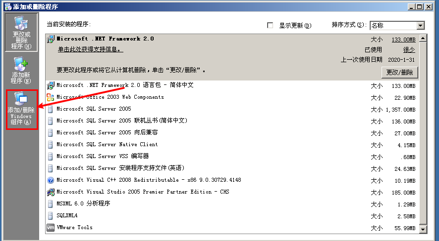
dns domain name resolution Start-Settings-Control Panel-Add/Delete, click to add/remove windows components (A) Check-network service, double click Just tick-domain name system (dns) and click O…

windows server 2003-iis
windows server 2003-iis Although there are a lot of information on the Internet that are better than what I wrote, I still write a little bit of my talk based on my iis, I think this can give me a dee…

windows server 2003-ftp
The ftp text transfer protocol is one of the important services on the Internet. The machine’s ip192.168.31.118 Install ftp first, start-settings-control panel-add delete Click-add and delete windows …

Configuring VPN with Windows Server 2003
(from: ) Configuring VPN with Windows Server 2003 Wednesday, March 05, 2008 10:54 AM Demand description The unit project team uses VSS (visual source safe 6.0C and visual source safe 200…
More Recommendation

Remotely install windows 2003 to the server
The remote server referred to in this article refers to the inability to physically touch, without a display, and without a keyboard. Server located in the equipment room 。 On the networ…

Windows server 2003 SSL configuration
SSL (Security Socket Layer) is a protocol that provides a secure channel between two hosts. The purpose is to protect the transmitted data by encryption and authenticate the two parties to ensure comm…
Windows 2003 Server Configuration FTP
A, IIS component is installed (provided) Here it is further ado, do not know can Baidu, or refer to my previous article station «Windows 2003 Server to build a website.» Second, configure th…

Windows server 2003 cluster construction
Windows server 2003 cluster construction A server cluster is a group of independent servers that run cluster services and work together as a system. The purpose of server clusters is to maintain clien…
Copyright DMCA © 2018-2023 — All Rights Reserved — www.programmersought.com User Notice
Top
- Remove From My Forums
-
Question
-
HOW TO CONFIGURE SERVER 2003 AS A ROUTER AND ALSO SHARE INTERNET CONNECTIVITY WITH OTHER CLIENTS ON THE NETWORK, I NEED HELP TO DO THE FOLLOWING, I HAVE 2 NIC ON MY PC , BUT I DONT KNOW HOW TO CONFIGURE THE SERVER SO THAT OTHER WORKSTATIONS CAN GET INTERNET
CONNECTION AND ALSO IP ADDRESSESI HAVE A FUNCTIONING NETWORK SYSTEM, ITS JUST THE INTERNET THING THAT I CANT SEEM TO GET
Answers
-
First, I would recommend that you simply purchase a consumer based router and have all of the computers including the server connect to the router ports or switch connected to the router. You’ll save alot of time and effort.
However, if you continue down the path of your intention, you simply need to enable Routing and Remote access on the 2003 server. Then add the Network Address Translation (NAT) service in RRAS. Assign the public NIC to public and private NIC
to private. The computers on the internal network will use the private NIC on the 2003 server as their default gateway.Here is the recommended design (you can replace the router in the picture with a 2003 server running RRAS)

Additional resources:
How to configure Network Address Translation in Windows Server 2003
http://support.microsoft.com/kb/816581Designing Active Directory for a SOHO Network
http://www.anitkb.com/2010/12/designing-active-directory-for-soho.html
Visit: anITKB.com, an IT Knowledge Base.
-
Marked as answer by
Friday, January 14, 2011 5:53 AM
-
Marked as answer by

Рассмотрим процесс настройки службы маршрутизации и удаленного доступа Windows Server 2003 в качестве маршрутизатора. Прежде чем приступить непосредственно к процедуре настройки, администратор должен решить следующие вопросы:
- выбрать протокол, для которого необходимо организовать маршрутизацию. Механизмы маршрутизации Windows Server 2003 позволяют организовать маршрутизацию протоколов IP и AppleTalk;
- определить, какой способ построения таблиц маршрутизации будет использоваться в корпоративной сети. В небольшой, редко изменяющейся сети наиболее простым и эффективным будет использование статической маршрутизации. В больших распределенных сетях с часто меняющейся структурой, предпочтительно использовать динамическую маршрутизацию;
- выбрать протоколы маршрутизации (в случае если используется динамическая маршрутизация). Данный пункт актуален для IP-трафика. Администратор может выбирать из двух протоколов маршрутизации — RIP и OSPF.
Рассмотрено программное обеспечение в качестве маршрутизатора информационной сети на базе серверной операционной системы Windows 2003.
В настоящее время очень остро стоит проблема обеспечение безопасности и надежности функционирования информационных сетей на предприятиях. В связи с этим возникает ряд задач, позволяющих решить данные проблемы, в частности: установка специального программного обеспечения, организация хранения данных, настройка программных маршрутизаторов и т.п.
Для решения означенных задач был выполнен анализ существующих программных средств и выделено применение сервера Windows 2003. основана задача данного сервера заключается в маршрутизации пакетов двух и более сегментов информационной сети. Анализ информации в интернете и специальной литературы не позволил однозначно выделить искомое решение, поэтому было решено исследовать данную проблему.
Маршрутизаторы являются ключевым звеном любой сети internetwork. Основные задачи, которые решают маршрутизаторы:
- нахождение наилучшего маршрута;
- отправка пакета по этому маршруту.
Маршрутизация сделала возможным объединение отдельных сетей в одну глобальную сеть, где каждому участнику сети доступны все ресурсы. Можно говорить о трех принципах маршрутизации:
- Каждый маршрутизатор принимает решение сам. При этом не оговаривается, откуда получена информация о маршрутах.
- Если один маршрутизатор имеет полную таблицу маршрутизации, то это не значит, что и у остальных она тоже полная. Можно привести много причин и примеров, когда сеть не сходится. В некоторых случаях это может привести к потере данных, а в некоторых и к циклам маршрутизации. Именно поэтому важно правильно и полно настроить статические маршруты на маршрутизаторах и/или правильно подобрать и настроить динамический протокол маршрутизации.
- Существование маршрута в одну сторону не гарантирует существование обратного маршрута. Простыми словами, пакет может достигнуть получателя, но обратного пути для ответного пакета может не быть. К этому приводит неполнота таблицы маршрутизации на каком-нибудь маршрутизаторе по пути.
Решением стало установка Windows Server 2003 на отдельном компьютере с двумя сетевыми картами, с установкой роли Routing и Remote Access Service (RRAS) на данной машине с дальнейшим использованием его в качестве маршрутизатора.
В первую очередь был настроен RRAS модуль в качестве роутера с трансляцией сетевых адресов (Network Address Translation – NAT). NAT является IETF стандартом, обеспечивающим способ трансляции IPv4 адресов компьютеров в одной сети в IPv4 адреса компьютеров в другой сети.
Начальная настройка, как и последующее администрирование, службы маршрутизации и удаленного доступа осуществляется через консоль управления. Для запуска консоли управления службой маршрутизации и удаленного доступа выбирается меню Пуск и в нем подменю Администрирование, в котором — пункт Маршрутизация и удаленный доступ (рисунок 1).
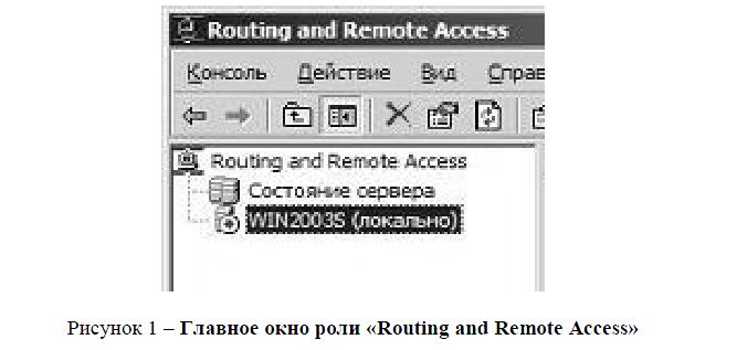
Рисунок 1 – Главное окно роли «Routing and Remote Access»
Первоначальная настройка сервера маршрутизации и удаленного доступа выполняется в дереве «Консоли управления», в меню «Маршрутизация и удаленный доступ» выбирается ветвь с именем локального сервера. Затем при нажатии правой кнопки мыши на имени сервера выбирается пункт «Настроить и включить маршрутизацию и удаленный доступ» из контекстного меню. Будет запущен Мастер настройки сервера маршрутизации и удаленного доступа. На первом шаге Мастера необходимо выбрать роль, которую будет выполнять сервер. Можно выбрать одну из следующих ролей:
Удаленный доступ (модем). При выборе данной роли, сервер со службой маршрутизации и удаленного доступа будет настроен для разрешения подключения удаленных клиентов к сети пользователя с помощью модема или другого оборудования удаленного доступа (рисунок 2).
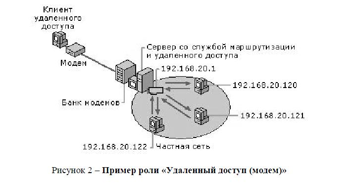
Рисунок 2 – Пример роли «Удаленный доступ (модем)»
Удаленный доступ (VPN). При выборе данной роли сервер со службой маршрутизации и удаленного доступа будет настроен для разрешения подключения удаленных клиентов к сети пользователя через Интернет (рисунок 3).
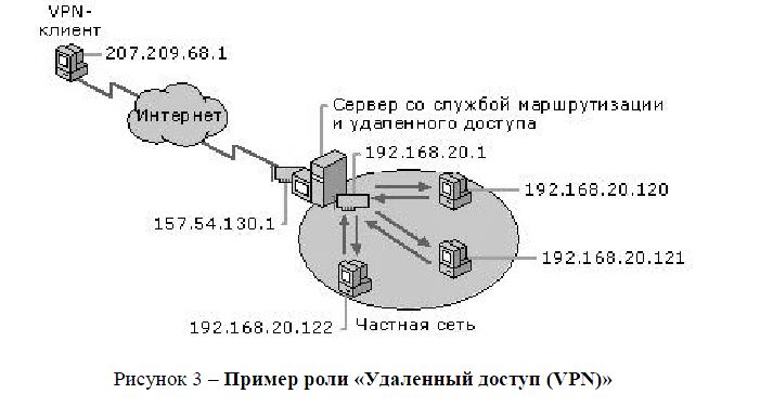
Рисунок 3 – Пример роли «Удаленный доступ (VPN)»
Преобразование сетевых адресов (NAT). При выборе данной роли, сервер со службой маршрутизации и удаленного доступа будет настроен для подключения к Интернету компьютеров частной локальной сети. Компьютеры, находящиеся в Интернете, не в состоянии определять IP-адреса компьютеров в сети пользователя (рисунок 4).
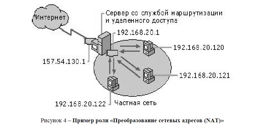
Рисунок 4 – Пример роли «Преобразование сетевых адресов (NAT)»
Виртуальная частная сеть (VPN) и преобразование сетевых адресов (NAT). При выборе данной роли сервер со службой маршрутизации и удаленного доступа будет настроен для подключения к Интернету компьютеров локальной сети пользователя и разрешения подключения удаленных клиентов к сети пользователя через Интернет. Компьютеры в Интернете не в состоянии определять IP-адреса компьютеров в частной сети. Однако клиенты VPN в состоянии подключаться к компьютерам сети пользователя, как если бы они были физически присоединены к этой сети (рисунок 5).
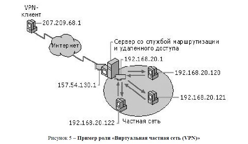
Рисунок 5 – Пример роли «Виртуальная частная сеть (VPN)»
Безопасное соединение между двумя частными сетями. При выборе данной роли два сервера со службой маршрутизации и удаленного доступа будут настроены для безопасной передачи частных данных через Интернет. Данный путь необходимо выбрать на каждом сервере при запуске мастера настройки маршрутизации и удаленного доступа. Подключение между двумя серверами может быть постоянным (включено постоянно) либо по требованию (вызов по требованию) (рисунок 6).
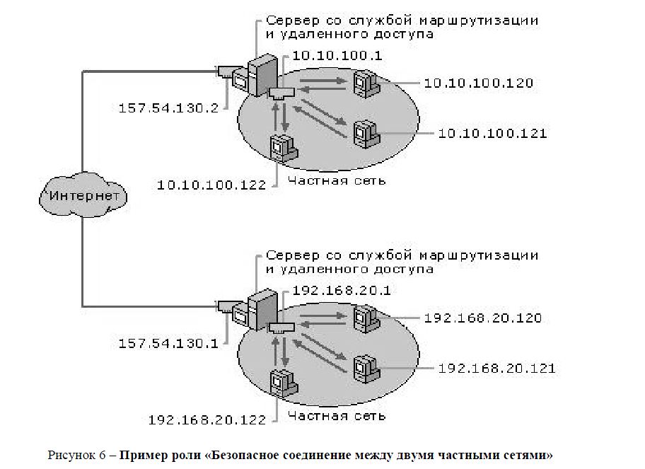
Рисунок 6 – Пример роли «Безопасное соединение между двумя частными сетями»
Управление IP-фильтрами. Маршрутизатор Windows Server 2003 поддерживает фильтрацию входящих и исходящих пакетов данных на различных уровнях:
- уровень физического интерфейса – фильтрация осуществляется для всех пакетов, проходящих через интерфейс, обычно это происходит после маршрутизации пакета;
- уровень интерфейса маршрутизации – фильтрация осуществляется при прохождении данных через интерфейс маршрутизации, при маршрутизации конкретного протокола;
- уровень клиента удаленного доступа – фильтрация данных осуществляется при передаче клиенту удаленного доступа по каналу связи.
На любом уровне фильтрация осуществляется отдельно для входящих и исходящих пакетов. Например, при передаче данных через маршрутизатор из локальной сети в Интернет для интерфейса подключения по локальной сети эти данные будут считаться входящими, а для интерфейса вызова по требованию – исходящими. Для клиентов удаленного доступа входящими всегда считаются данные, передаваемые клиентом, а исходящими – данные, передаваемые клиенту.
В интерфейсе управления маршрутизатором Windows Server 2003 входящие фильтры обычно настраиваются кнопкой «Фильтры входа», а исходящие – кнопкой «Фильтры выхода». Покажем настройку фильтров на примере входящих фильтров. Настройка исходящих фильтров осуществляется аналогично.
В окне «Фильтры входа» указывается набор действующих фильтров и условия фильтрации. Последние определяются переключателем в верхней части окна, который может быть установлен в одно из положений:
- Не разрешать перечисленные пакеты. Через фильтр пропускаются все пакеты, кроме тех, которые отвечают условиям, указанным в списке «Фильтры».
- Разрешать только перечисленные пакеты. Через фильтр пропускаются только те пакеты, которые отвечают условиям, указанным в списке «Фильтры».
Набор условий для проверки задается в списке «Фильтры». Для добавления условия в список необходимо щелкнуть кнопку «Создать» (рисунок 7).
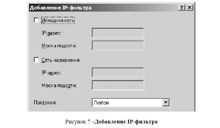
Рисунок 7 –Добавление IP-фильтра
В данном окне необходимо задать параметры исходного и конечного адреса проверяемого пакета. Если должен анализироваться адрес отправителя, то необходимо установить флажок «Исходная сеть» и указать адрес и маску сети отправителя. Если должен фильтроваться только один определенный IP-адрес, его необходимо указать в поле IP-адрес, а в поле «Маска» указать значение 255.255.255.255. По аналогии настраивается анализ адреса получателя.
В раскрывающемся списке «Протокол» должен быть выбран протокол, пакеты которого анализирутся фильтром. При указании протоколов TCP или UDP необходимо дополнительно задать диапазон исходящих и входящих портов. Например, для выделения всех запросов к Web-серверу локальной сети (адрес 192.168.0.10) должен задаваться фильтр со следующими параметрами:
Для поставленной задачи была выбрана роль RRAS «Преобразование сетевых адресов (NAT)» для работы маршрутизатора.
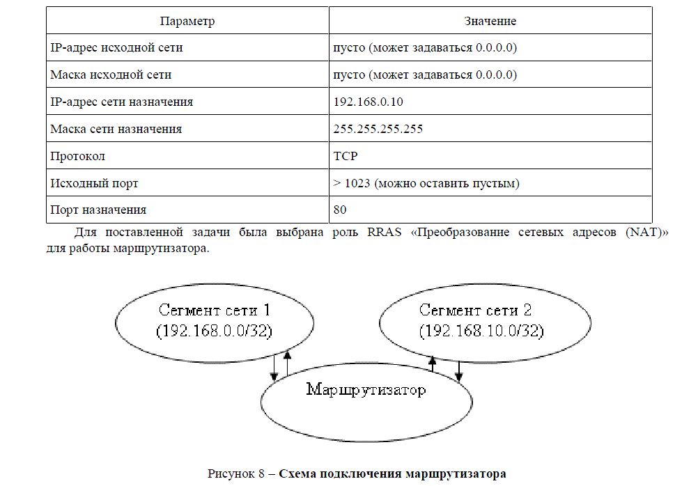
Рисунок 8 – Схема подключения маршрутизатора
Windows Server 2003 был установлена на машину с двумя сетевыми картами, параметры TCP/IP этих карт были настроены следующим образом:
Сетевой интерфейс Realtek подключен к основной сети:
— IP адрес = 192.168.10.1;
— Маска подсети = 255.255.255.0;
— Основной шлюз = 192.168.10.1;
— DNS серверы = 192.168.0.250.
Сетевой интерфейс NIC подключен к сегменту сети:
— IP адрес = 192.168.0.250.
— Маска подсети = 255.255.255.0.
— Основной шлюз = 192.168.0.2.
— DNS серверы = 212.154.163.162.
Установка клиентских компьютеров в основной сети LAN.
Установки на клиентских машинах: для сегмента сети были назначены DHCP-сервером и были следующие:
- IP адрес = 192.168.10.0/32.
- Маска подсети = 255.255.255.0.
- Основной шлюз = 192.168.10.1 (ближайший интерфейс сервера RRAS).
- DNS серверы = 192.168.0.250(DNS сервер домена).
Таким образом, маршрутизатор стал связующим звеном между сегментом сети и основной сетью (рисунок со своими правилами адресации в сети и настройками безопасности. При такой настройке в сегмент сети нет необходимости вводить для каждой машины сетевые правила подключения к серверам или обращения за пределы сегмента сети, маршрутизатор работает на правилах, созданных для работы в сети на основе фильтров, установленных администратором сети.

on
September 16, 2004, 12:00 AM PDT
SolutionBase: Using Windows Server 2003 as a router on your network
Windows Server 2003 has many powerful features, including a built-in router. Here’s how you can configure Windows Server 2003 to act as a router on your network.
Windows Server 2003 has many powerful features, including a
built-in router. Why would you want to use Windows Server 2003 for routing? Because
you can? Okay, that’s not really a good answer. But you’ve probably wondered
why you’d use Windows Server 2003 as a router rather than using a
dedicated router from Cisco, Bay Networks, or another manufacturer. In a lot of
situations, a dedicated router makes more sense and is generally less
expensive. There are situations, however, where it makes sense to use Windows
Server 2003 for routing. Here’s how you can configure Windows Server 2003 to
act as a router on your network.
How Windows Server 2003 routing works
Windows Server 2003’s RRAS service supports several
capabilities, one of which is supporting dial-up clients through
POTS, ISDN, and other connectivity options. You can use integrated Windows
authentication or rely on a RADIUS server (which could be the RRAS server) to
authenticate clients. PPTP and L2TP support enable the RRAS server to function
as a VPN server, giving remote clients a means of establishing a secure,
private network connection to the LAN through a public network such as the
Internet. Typically, the VPN connections come in through a dedicated, 24/7
Internet connection.
For example, assume you have three network segments, which
currently are not interconnected, and you’re setting up a remote access server
on one of those segments. At the same time, you want to provide dial-up
capability to each segment by remote clients. In this situation, it makes sense
to install a single RAS server and let it provide routing services to all
segments. Windows Server 2003 can fulfill both roles with no problem. So, using
Windows Server 2003 as a router makes sense when you’re providing services to
your LAN that require routing and no other routers are currently online to
handle the traffic, or you don’t want the additional expense and management of
a dedicated router in addition to your server.
Another reason to use Windows Server 2003 for routing is to
provide DHCP Relay services for DHCP clients that reside on network segments
where there is no DHCP server. Windows Server 2003 includes a DHCP Relay agent
that provides this functionality in conjunction with RRAS.
A third reason to use Windows Server 2003 RRAS for routing
is ease of use. Although router manufacturers have come a long way toward
improving the configuration and management interfaces for their routers, the
GUI management tools in Windows Server 2003 make it very easy to configure and
manage Windows Server 2003 routers.
A Windows Server 2003 RRAS server can function as a
dedicated router, connecting other routers continuously, or it can function as
a demand-dial router. In this latter scenario, the router dials and connects to
a remote router only when traffic that requires routing to the remote network
comes to the router. Demand-dial routing is often used to reduce connectivity
costs. If you send traffic over a metered connection only once or twice a day,
for example, why pay for a full-time connection? With demand-dial routing, the
router dials the remote network when traffic needs to be routed, then
disconnects automatically after a defined period of inactivity. This helps keep
costs down by keeping the connection live only when needed.
Understanding IP routing
Without IP routing, the Internet and many private networks
would stop functioning instantly. Routing is a crucial aspect of IP networking.
Understanding how routing works is the place to start when you’re thinking
about setting up a Windows Server 2003 RRAS server to function as a router.
The primary function of a router, whether it is a dedicated
box or a Windows Server 2003 router, is to route network packets between
different network segments. When you open a browser to connect to a Web site,
for example, your computer looks up the IP address of the remote site through
DNS and then sends network packets to the remote site’s IP address to request
the site’s content.
Your network router, identified by your workstation at its
default gateway, receives the traffic, analyzes the destination IP address for
the packets, and determines that the packets are destined for a network segment
beyond your own. Based on its routing tables, the router sends the packet out
on the appropriate interface to another router. The traffic gets routed through
potentially several routers and eventually reaches the server where the site is
hosted. Then, the process happens again in reverse for the traffic coming from
the server to your computer.
Routers generally are connected to at least two subnets and,
in effect, the router resides as a node in each of the subnets to which it is
connected. This gives the router local connectivity to each of the subnets on
which it resides and is the mechanism by which routing is possible. Figure A illustrates a router connected
to three different subnets, which in turn are connected to other subnets and
eventually the Internet. Each router is sometimes referred to as a “hop,” and a
packet’s hop count is increased by one each time it passes through another
router (more about this later).
|
Figure A |
 |
| An example of a router connected to multiple subnets |
As the figure illustrates, Router A connects subnet 1 to
subnets 2 and 3, which are in turn connected to the Internet by other routers,
B and C. Router A therefore is assigned three IP addresses, one in each subnet,
making it a member of each subnet and directly accessible to the nodes in each
connected subnet. When a client in subnet 1 sends traffic destined for subnet
3, the traffic is directed to the client’s default gateway, which in this case
is the IP address of the router at A1. The default gateway is defined in the
client computer’s TCP/IP properties.
The router analyzes the packets when they come in to
determine the destination address. Discovering that the traffic is destined for
subnet 3, the router directs the traffic out the interface A3, based on its
internal knowledge that the destination node must reside on subnet 3.
But what happens when the traffic is destined for a subnet
that resides beyond the router’s locally connected segments, such as a remote
Internet server? The router uses its routing table to determine which interface
to use to route the traffic. The router’s default route, which you configure,
is the route used when traffic is destined for an address that resides beyond
the router’s local interfaces. The default route specifies the IP address of
the router to which all traffic that isn’t destined for a known interface (also
determined by the routing table) should be routed. So, the router analyzes the
packet, recognizes that the destination IP address doesn’t match the subnets of
defined routes in the routing table, and directs the packet to the default
route. The router specified by the default route analyzes the packet and routes
it based on its routing table.
Each route in a routing table falls into one of three
categories:
-
Network
route: Provides a route to a specific network ID and all addresses within
that network -
Host
route: Provides a route to a specific host (A host route entry defines the
host IP address as well as the network address.) -
Default
route: Used to route traffic for which there is no corresponding network
route or host route
The routing table contains routing entries against which the
router checks the destination address of all packets to determine how to route
each packet. Each entry in the routing table has specific general properties:
-
Network
ID, host address, subnet mask: These properties serve to identify the
destination network ID or host address and the destination’s subnet. If the
router determines that the destination address stored in the packet’s header
matches these properties in a routing table entry, it forwards the packet to
the forwarding address associated with the route (see next). -
Forwarding
address: This is the address of the remote router to which the router
forwards packets that match the network ID, host address, or subnet defined by
the entry. -
Interface:
This property specifies the local router port through which the traffic
should be routed for packets that satisfy the criteria of the routing table
entry. -
Metric:
This value identifies the relative cost of the route, which is based on actual
connection cost, available bandwidth, and other factors that you determine when
you create a route. If more than one route exists for the same destination, the
router uses the one with the lowest metric, if available.
Here’s a summary of the whole process: A packet comes into
the router. The router analyzes the destination address in the packet’s header.
The router then examines its routing table, attempting to match the packet’s
destination address against the network ID, host address, or subnet properties
of each routing table entry. If a match is found, the router directs the packet
to the forwarding address defined by the matching routing table entry, using
the interface and metric to decide how to physically route the packet out of
the router. If the packet’s destination address doesn’t match any of the
routing table entries, the router sends the packet to the forwarding address
defined by the router’s default route. If no default route is defined, the
packet is rejected and routing fails. The routing table is therefore the
blueprint by which the router accomplishes its job.
How are routing entries added to the routing table? A router
can learn its routes dynamically from other routers, or it can use statically
defined routes, or static routes. With dynamic routes, routers communicate with
one another to share learned routes, which enables routes to propagate to
adjacent routers. Routing protocols are used to enable the routers to share
this routing information. The two most common routing protocols are Routing Information
Protocol (RIP) and Open Shortest Path First (OSPF), both of which are supported
by Windows Server 2003.
The administrator who configures the router creates static
routes manually. In a small network with few subnets, static routes are an
effective means of routing all traffic. As the number of routers grows,
however, dynamic routing becomes more desirable because of the reduced
management overhead. You don’t have to manage existing routes or create new
ones when another segment is added to the network. Instead, the router learns
its routing table from adjacent routers automatically when the router comes
online.
Overview of RIP
Of the two routing protocols included with Windows Server
2003, RIP is easier to configure. RIP is limited to a maximum hop count of 15,
making RIP useful for small- to medium-size installations. Any address more
than 15 hops away is deemed unreachable by the router.
Each time a router boots, it re-creates its routing table.
The routing table initially only contains the routing table entries for
physically connected networks. A router using RIP periodically broadcasts
announcements regarding routes, which enables adjacent routers to modify their
routing tables. So, after a router comes online, it begins using RIP announcements
to build its routing table. Also, RIP provides for triggered updates in
addition to broadcast updates. These triggered updates occur when a router
detects a network change, such as an interface going down. The router then
broadcasts the change to adjacent routers, which modify their routing tables
accordingly. When the interface comes back up, the router that recognizes the
change broadcasts a triggered update to adjacent routers, which again modify
their routing tables to accommodate the change.
Windows Server 2003 supports RIP version 1 and version 2.
RIP v2 provides additional features over RIP v1, such as authentication for
security and route filtering. RIP v2 also supports multicast broadcast of RIP
announcements and several other features. RIP v1 routers are forward-compatible
with RIP v2 routers, enabling them to coexist.
Overview of OSPF
OSPF was developed to address the needs of large networks,
such as the Internet. Each OSPF router maintains a link-state database (LDB)
that contains link-state advertisements (LSAs) from adjacent routers. The LSA
contains information about a router, its connected networks, and configured
costs. The cost is similar to a route metric discussed earlier, in that it
defines the relative cost of using the route. OSPF uses an algorithm to
calculate the shortest path for routing based on the information contained in
its LDB, making it a very efficient means of routing. Adjacent routers
recalculate and synchronize their LDBs as network changes occur, such as
network interfaces going down or coming online.
OSPF is more complicated to configure than RIP. Its
performance advantages are geared primarily toward very large networks, so if
you’re setting up a router for a small- or medium-size network, RIP is
generally the better option. Where network size is a factor, however, OSPF is
the better choice.
Unicast routing vs. multicast routing
Another important aspect to understand about routing is the
difference between unicast routing and multicast routing. In unicast routing, a
packet is sent from one node to only one other node, as illustrated in Figure B. This is the most common type
of routing and the one you use every time you open a Web browser and browse an
Internet site, retrieve your e-mail, move a file with ftp, and perform most
other common IP-based network tasks.
|
Figure B |
 |
| Unicast routing directs packets from one node to another. |
In multicast routing, however, traffic is broadcast from one
node to many nodes, as illustrated in Figure
C. Multicasting is most commonly used for audio and video conferencing,
enabling packets to be efficiently transmitted to multiple clients from a
single host. Without multicasting, the packets would have to be transmitted
multiple times to each client, generating a considerably larger amount of
network traffic and imposing more overhead on the server. Plus, as you can
imagine, conferencing would be difficult to set up without multicasting, as the
conferencing server would need to be preconfigured with the list of all
participants. With multicasting, the participants simply listen on a designated
multicasting address, which can be allocated by a DHCP server to automate
configuration.
|
Figure C |
 |
| Examples of conferencing with and without multicasting |
Configuring a unicast router
As with other RRAS configurations, you can use the RRAS
wizard to configure Windows Server 2003 as a router. Setup installs RRAS by
default, so you only need to enable and configure the server according to your
routing needs. To start the RRAS wizard, open the RRAS console from the
Administrative Tools folder. Right-click the server and choose Configure And
Enable Routing And Remote Access. In the wizard, select the option to configure
a network router. The wizard prompts you for the following information:
-
Protocols:
Select the protocols to be supported for routing, such as TCP/IP and/or IPX. If
the protocols are not installed, the wizard gives you the option of adding
them. By default, all installed protocols are enabled for routing, but you can
choose to disable some if you don’t want the protocol to be routed. -
Use
demand-dial connections: You can choose to enable demand-dial routing at
this point or accomplish the task later.
In addition to configuring the router through the wizard,
you also can enable routing manually. You need to choose this latter option if
the server is already configured and enabled for RRAS (such as a VPN server)
and you want to add routing to the server’s list of roles.
To enable routing for a server that already has RRAS
enabled, open the RRAS console from the Administrative Tools folder.
Right-click the server and choose Properties. Select the Router check box and
then select the type of routing you want to support, either LAN or LAN and
demand-dial. Then click OK.
Next, configure the IP address for which RRAS performs
routing on that interface. By default, Windows Server 2003 uses the first
interface to process routing tasks on that interface, and on interfaces with
only one address, no configuration is needed. If the interface has multiple
addresses, however, you’ll need to reconfigure RRAS if the default address is
not the one you want to use. To configure the address, open the RRAS console,
expand the server, and expand the IP Routing branch. Click General and, in the
right pane, right-click the interface you want to modify and choose Properties.
Use the Configuration page to set the IP address, subnet mask, and default
gateway (if needed) for the interface. To set the metric for the interface,
click Advanced.
Configuring a router with static routes
At this point, I assume you have the server enabled for
routing and have configured the desired address on each interface. Now it’s
time to think about how you’ll implement routing. As mentioned earlier, you can
use static routes, RIP, or OSPF (if the router only routes traffic between two
subnets, you don’t need to worry about creating routes or using RIP or OSPF).
Let’s take a look at static routes, which are a good option if you’re setting
up your Windows Server 2003 RRAS router in a small network.
For this example, we’ll use privately addressed network
segments. Figure D shows our sample
network structure. We’ll work on configuring router B, which we’ll assume has
two network interfaces. As Figure D illustrates, router B resides on subnets
192.168.0.n and 192.168.1.n. The IP addresses of the router’s interfaces are
192.168.0.20 (LAN 0) and 192.168.1.1 (LAN 1). In these examples, I’ve renamed
the network interfaces from their default names of Local Area Connection and
Local Area Connection 2 to LAN 0 and LAN 1, respectively. It’s a good idea on
multihomed systems to rename the interfaces to help you keep track of what’s
what. To rename the interfaces, open the Network And Dial-Up Connections
folder, right-click an interface, and choose Rename.
|
Figure D |
 |
| Sample network for configuring routing |
Let’s add a static route at Router B to route traffic to the
192.168.2.0 subnet (subnet 2) through interface LAN 1. To add a static route,
first open the RRAS console. Expand the IP Routing branch and click Static
Routes. Either right-click in the right pane or right-click Static Routes and
choose New Static Route. RRAS displays the Static Route dialog box in which you
provide the following data:
-
Interface:
Choose the network interface that RRAS should use to route traffic that meets
the static route criteria. In this example, you want to configure a static
route for traffic destined for 192.168.2.0 to be routed through LAN 1, so
select the LAN 1 interface. -
Destination:
Rather than create a host route, you’ll create a network route. Enter the
network ID of the destination network, which in this example is 192.168.2.0.
Remember that the router compares the destination IP address of incoming
packets against this network address to determine if the route entry matches
and if the route is appropriate for routing the packets. You can specify a network
address, host address, or use 0.0.0.0 for this value (this latter option
creates a default route). Use the low network address to specify a network
address, as I did in this example, or specify the actual IP address of the host
if creating a host route. -
Network
mask: Specify the subnet mask of the destination network or host. In this
example, enter 255.255.255.0, the subnet mask for our Class C private network. -
Gateway:
Specify the IP address to which packets matching the route criteria are routed.
In this example, you need to specify the IP address of Router C on the
192.168.1.0 subnet. As you can see from Figure D, the address to enter is
192.168.1.2. -
Metric:
Enter the relative cost for the route by specifying a metric. If more than one
route exists, the one with the lowest metric is used to route the traffic if
that route is available. -
Use this
route to initiate demand-dial connections: If you have configured at least
one demand-dial interface for the router, this option is available. Select this
option if you want the router to initiate a demand-dial connection when it
receives traffic that matches the selected route.
Next, you create a static route to accommodate the
192.168.3.0 subnet. The data for this static route is the same as the one you
just created, except the destination network address is 192.168.3.0. The
Gateway is the same as in the previous route. The static routes you set up on
Router C handle the traffic from that point, routing it to Router D.
Finally, you should create a default route on Router B that
directs all other traffic not destined for subnets 1, 2, or 3 to Router A, with
the assumption that the traffic is destined for a public address on the
Internet. So, create another static route on Router B using the following
values:
-
Interface:
LAN 0 -
Destination:
0.0.0.0 -
Network
mask: 0.0.0.0 -
Gateway:
192.168.0.1 -
Metric:
As desired -
Use this
route to initiate demand-dial connections: As needed
It’s not all that bad
You can see that setting up static routes takes a little
work but can be an effective means of configuring routing for small networks.
As the number of routers you manage grows, you’ll likely turn to RIP and/or
OSPF to provide dynamic routing. While RIP and OSPF are a little more
complicated to set up, they are much easier to manage. In an upcoming article,
we’ll take a detailed look at both protocols, as well as demand-dial routing
and multicast routing.
Администрирование
Microsoft
Windows
Server
2003
Лабораторная
работа № 3
2013
Лабораторная
работа № 3.
Маршрутизация в IP-сетях
Цели работы:
-
научиться объединять
две сети при помощи компьютера,
исполняющего роль маршрутизатора; -
научиться
настраивать Windows
Server
2003 в качестве маршрутизатора; -
изучить возможности
утилиты route.
Связь с проектом
Часто возникают
задачи, когда необходимо к локальной
сети подключить другую локальную сеть,
причем номера подсетей у них разные.
Например, возникла потребность к сети
факультета информационных технологии
(ФИТ) подключить сеть юридического
факультета (ЮФ). ФИТ имеет подсеть с
номером 10.1.1.0/24, а ЮФ – подсеть 10.1.2.0/24.
Каким образом сделать так, чтобы, не
меняя номера подсетей, компьютеры обоих
факультетов могли соединяться друг с
другом и использовать общие ресурсы?
Данная задача
решается при помощи настройки
маршрутизатора, соединяющего обе
подсети, причем в роли маршрутизатора
может выступать компьютер с Windows
Server
2003, имеющий две сетевые карты: одна
подключена к сети факультета информационных
технологии, другая – к сети юридического
факультета. В результате требуется
получить следующую схему сети рис.2:
Рис.
2. Схема сети с маршрутизатором
Внимание!!! Если
на физическом компьютере, на котором
выполняется лабораторная работа, Вы не
являетесь членом группы администраторов,
вместо физического компьютера используйте
вторую виртуальную машину Windows
XP.
В этом случае создайте копию машины в
меню Virtual
Box
выберите машина – Копировать. Сгенерируйте
MAC
– адрес новой машины, поменяйте её имя
и IP-адрес.(В
том случае настройте все используемые
адаптеры как Внутренняя
сеть)
Задание 1.
Переместить виртуальную машину с Windows
XP
в другую подсеть с номером 10.1.2.0/24.
Указания к
выполнению
-
Подключите
виртуальную машину с Windows
XP
к внутренней сети виртуальных машин:
в разделе Сетевые
параметры
настроек виртуальной машины выберите
подключение сетевого адаптера к
внутренней сети виртуальных машин.
Таким образом,
образовалось две физические подсети
(см. рис. 2).
-
Запустите
виртуальную машину с Windows
XP.
Измените сетевые параметры виртуальной
машины следующим образом:
-
IP-адрес:
10.1.2.20; -
маска подсети:
255.255.255.0.
Таким образом,
виртуальная машина находится сейчас в
подсети 10.1.2.0/24.
-
Поместите в отчет
окно с установленными сетевым
параметрами.
-
Проверьте, что
виртуальная машина не
способна
установить соединение с физическим
компьютером с помощью утилиты ping:
ping
10.1.1.10
-
Поместите в отчет
скриншот окна командной строки с
информацией о невозможности установить
соединение.
Задание 2.
Настроить виртуальную машину с Windows
Server
2003 в качестве маршрутизатора.
Указания к
выполнению
-
Установите два
сетевых адаптера на виртуальную машину
с Windows
Server
2003 (Раздел Сетевые
параметры
настроек
виртуальной машины). Подключите первый
адаптер как Внутренняя
сеть
виртуальных машин, второй – к Внутренний
адаптер хоста. -
Запустите
виртуальную машину. Откройте окно
Сетевых
подключений.
В этом окне должно быть два подключения
по локальной сети, первое из них
(Подключение
по локальной сети)
соответствует
тому адаптеру, который подключен к
внутренней сети виртуальных машин,
второе (Подключение
по локальной сети 2)
соответствует
адаптеру
Внутренний
адаптер хоста -
Настройте IP-адреса
обоих подключений согласно рис. 1.
Проверьте, что физический компьютер
имеет соединение с сервером и наоборот,
а также, что виртуальная машина c
Windows
XP
имеет связь с сервером и наоборот. При
этом физический компьютер и виртуальная
машина c
Windows
XP
соединиться не могут, так как находятся
в разных подсетях.
-
Поместите в отчет
скриншот окна командной строки с
информацией о невозможности установить
соединение.
-
На виртуальной
машине с Windows
Server
2003 настройте службу маршрутизации. Для
этого откройте оснастку Маршрутизация
и удаленный доступ: Пуск –
Программы –
Администрирование –
Маршрутизация и удаленный доступ. -
В контекстном
меню сервера выберите пункт
Сконфигурировать
и активировать маршрутизацию и удаленный
доступ.
В окне
мастера выберите пункт Выборочная
конфигурация.
Установите
флажок
Маршрутизация
ЛВС.
На
предложение запустить службу нужно
ответить ДА. -
Просмотрите
таблицу маршрутизации, действующую
сейчас на сервере: щелкните на значке
сервера, затем на IP
маршрутизация,
в контекстном
меню элемента Статические
маршруты
выберите Показать
таблицу маршрутизации.
Эта таблица соответствует той таблице,
которая выводится в командной строке
при запуске утилиты route
с ключом /print.
-
Сохраните в отчете
скриншот с таблицей, полученной из
оснастки и скриншот с таблицей,
полученной с помощью утилиты route.
-
Теперь следует
добавить в таблицу маршрутизации
записи, которые позволят компьютерам
из разных подсетей связываться друг с
другом. В контекстном меню элемента
Статический
маршрут
выберите
пункт Новый
статический маршрут.
В появившемся окне введите следующие
параметры:
-
Интерфейс
– Подключение
по локальной сети; -
Адрес
назначения
–
10.1.2.0; -
Маска
подсети
– 255.255.255.0; -
Шлюз
– 10.1.2.1; -
Метрика
– 1.
Таким образом,
настроен маршрут для передачи пакетов
из подсети 10.1.2.0 в подсеть 10.1.1.0.
Создайте ещё
один статический маршрут и по аналогии
настройте его для передачи пакетов из
подсети 10.1.1.0 в подсеть 10.1.2.0.
-
Поместите в отчет
скриншоты с окнами обоих маршрутов и
результат в окне Статические маршруты.
-
Просмотрите
созданные записи в разделе Статические
маршруты. и в таблице маршрутизации.
Задание 3.
Осуществить подключение виртуальной
машины с Windows XP
к физическому компьютеру через
маршрутизатор.
Указания к
выполнению
-
Настройте для
виртуальной машины с Windows
XP
шлюз по умолчанию в соответствии с
рис. 4. Для этого откройте окно настроек
параметров TCP/IP
(то окно, в котором следует менять
IP-адрес
компьютера). В строке Основной
шлюз
введите IP-адрес
10.1.2.1.
-
Сохраните скриншот
окна в отчете.
-
Проверьте (с
помощью утилиты Ipconfig),
что на физическом компьютере установлен
шлюз по умолчанию 10.1.1.1. Если это не так,
измените шлюз по умолчанию.
-
Сохраните скриншот
окна в отчете.
-
Проверьте
способность виртуальной машины с
Windows
XP соединяться с физическим компьютером
с помощью утилиты ping. -
Аналогичным
образом проверьте способность физического
компьютера соединяться с виртуальной
машиной.
-
Поместите скриншоты
командной строки в отчет. Запишите в
отчете выводы.
Задание 4.
Вернуть исходные настройки.
1.
Верните следующие настройки:
-
IP-адрес
виртуальной машины с Windows
XP; -
количество сетевых
карт виртуальной машины с Windows
Server 2003
сделайте равным 1; -
подключите сетевую
карту виртуальной машины с Windows
Server 2003
к
Внутренний
адаптер хоста.
Самостоятельная
работа
Объедините две
подсети 10.1.1.0/24 и 10.1.2.0/24 при помощи
маршрутизатора на основе виртуальной
машины с Windows
XP.
В этом случае для просмотра таблицы
маршрутизации, добавлении и удалении
новых маршрутов придется использовать
исключительно утилиту route.
-
Зафиксируйте
процесс объединения в отчете с помощью
скриншотов, аналогично тому, как делали
в работе.
Контрольные
вопросы
-
Назовите протоколы
маршрутизации, реализованные в Windows
Server
2003. -
Что такое таблица
маршрутизации? -
Какие записи
создаются в таблице маршрутизации по
умолчанию? -
Чем отличаются
возможности Windows
Server
2003 от возможностей Windows
XP
в области маршрутизации? -
Какое максимальное
количество сетей можно соединить,
используя один компьютер с Windows
Server
2003 в качестве маршрутизатора?