Всем привет! Сегодня разберёмся как работает wi-fi.
Задачи лабораторной работы: 1)знакомство со стандартами wi-fi; 2) изучение способов использования wi-fi (маршрутизация и точка доступа);
Создание модели
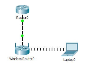
Создать модель локальной сети, состоящей из обычного домашнего wi-fi роутера и маршрутизатора, который имитирует провайдера Интернета. Использовать интерфейс Fast Ethernet. Добавим ещё пользовательское устройство, например ноутбук. Установим модуль wi-fi (WPC300N) в ноутбук.

Настройка модели
1)Настройки маршрутизатора провайдера Router0 (жирным выделено то, что необходимо ввести с клавиатуры:
Router>en
Router#
Router#conf t
Enter configuration commands, one per line. End with CNTL/Z.
Router (config)#int fa0/0
Router (config-if)#ip address 210.210.0.1 255.255.255.252
Router (config-if)#no shutdown
Router (config-if)#
%LINK-5-CHANGED: Interface FastEthernet0/0, changed state to up
%LINEPROTO-5-UPDOWN: Line protocol on Interface FastEthernet0/0, changed state to up
Router (config-if)#end
Router#
%SYS-5-CONFIG_I: Configured from console by console
Router#wr mem
Building configuration…
[OK]
2)Настройки домашнего wi-fi маршрутизатора Wireless Router0
выполняется с помощью веб интерфейса.
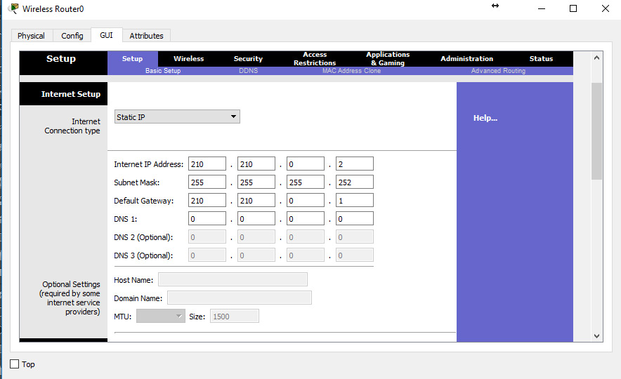
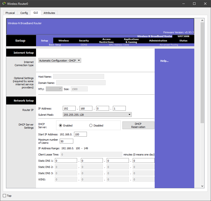
Настройка внешнего интерфейса во вкладке Setup показана на рисунке.
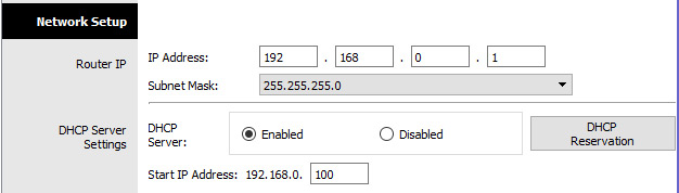
Настройка локальной сети (Network Setup)
Выбираем по умолчанию ip-адрес 192.168.0.1, маска 24-битная 255.255.255.0, разрешён DHCP-сервер, начало раздачи с адреса 192.168.0.100 и всё. После чего незабываем сохранить настройки, нажать на кнопку внизу формы Save Settings.
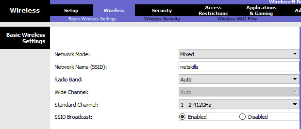
Настройки во вкладке Wireless, т.е. wi-fi. Выбираем основные настройки вайфая: режим (mode), мы выбираем смешанный (mixed); идентификатор сети (SSID) — netskills; ширина канала (Radio Band) — auto; частоту — 1-2.412HGz; видимость сети (SSID Broadcast) — видимая (enable). Сохраняем настройки.
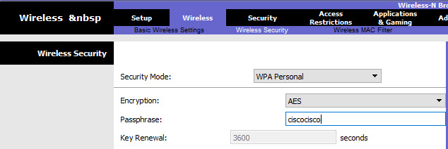
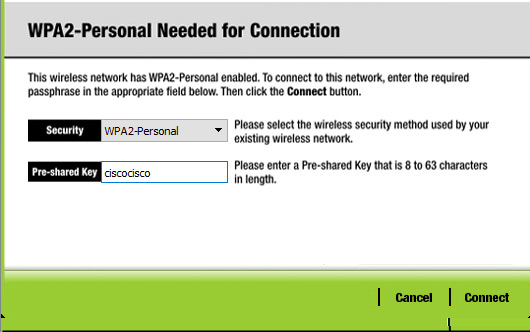
Переходим ко вкладке Wireless Security. Выбираем режим шифрования WPA2 Personal, алгоритм шифрования AES, ключевое слово для выбранного режима шифрования не менее 8 символов. Сохраняем.
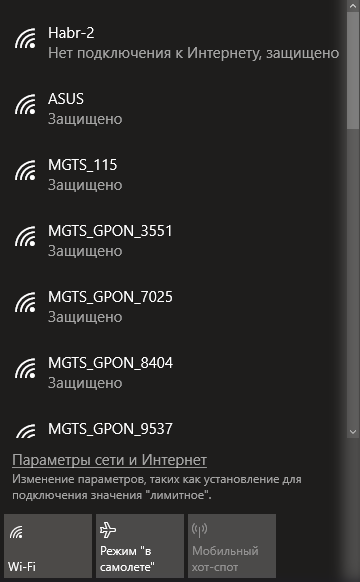
3)Настройка wi-fi адаптера на ноутбуке. Вкладка Desktop->PC Wireless->Connect. Смотрим доступные нам сети. Нажимаем кнопку Connect для подключения к сети netskills.
Если настройки произведены верно, то появиться пунктирная линия между wi-fi маршрутизатором и ноутбуком как на рисунке.
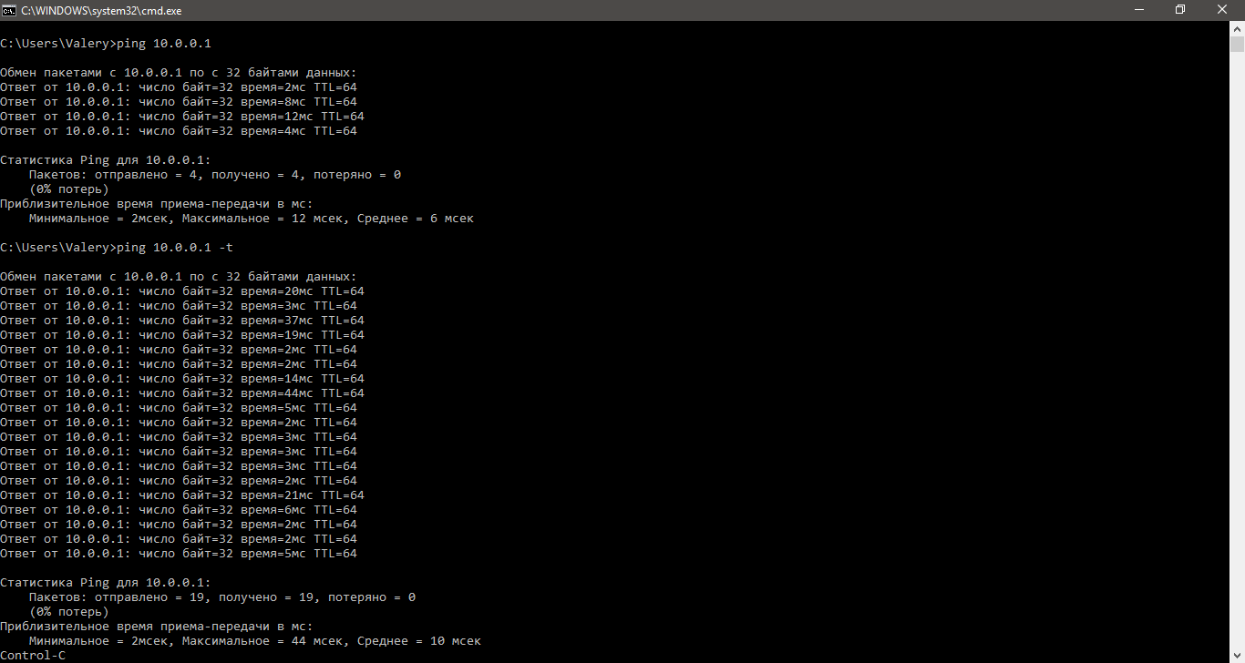
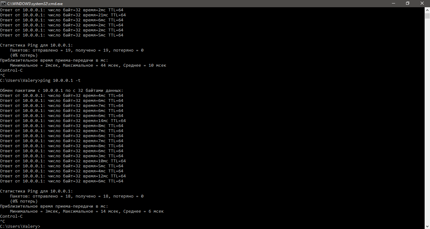
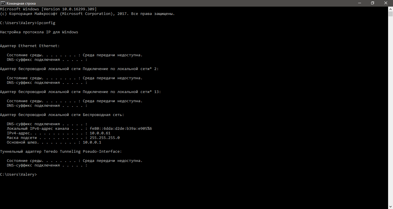
Введём на ноутбуке в командной строке команду ipconfig, чтобы проверить правильность настроек. Из рисунка видно, что DHCP- сервер присвоил правильный ip 192.168.0.100 Пропингуем шлюз (wi-fi маршрутизатор) и пропингуем адрес интернет провайдера. На рисунке видно, что в обоих случаях пинг идёт.
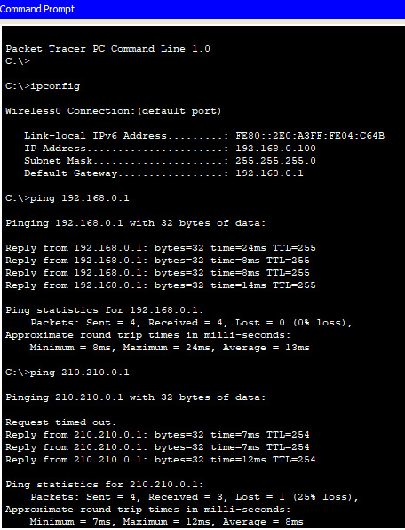
При этом NAT мы не использовали, так как практически на всех wi-fi маршрутизаторах NAT используется по умолчанию.
Если у вас возникли трудности с выполнением задания, вы всегда сможете найти толкового исполнителя здесь: work-zilla.com

Готовая лабораторная работа wi-fi
Лабораторная работа №6 Создание простейшей сети
Кол-во просмотров: 54387
Время на прочтение
9 мин
Количество просмотров 65K
Введение
В данной статье в лабораторных работах изучается технология беспроводных локальных сетей по стандарту IEEE 802.11. Стандарт IEEE был разработан институтом инженеров по электротехнике и электронике (Institute of Electrical and Electronic Engineers). Отсюда он и получил своё название. Данный стандарт определяет локальные сети Ethernet; поэтому модель TCP/IP не определяет сети Ethernet в своих запросах на комментарии, а ссылается на документы IEEE Ethernet. Все работы будут выполняться в программе Cisco Packet Tracer.

Концепция беспроводных сетей
Многие пользователи регулярно пользуются услугами и устройствами беспроводных локальных сетей (Wireless LAN — WLAN). На текущий момент времени растёт тенденция использования портативных устройств, таких как ноутбуки, планшеты, смартфоны. Также сейчас активно развиваются концепции «умного дома», большинство устройств которого подключаются «по воздуху». В связи с этим возникла потребность беспроводного подключения во всех людных местах: на работе, дома, в гостинице, в кафе или книжном магазине. С ростом количества беспроводных устройств, которые подключаются через сеть WLAN, выросла популярность беспроводных сетей.
Ниже представлена упрощённая схема работы сети в «Доме книги» на Невском проспекте в Санкт-Петербурге.
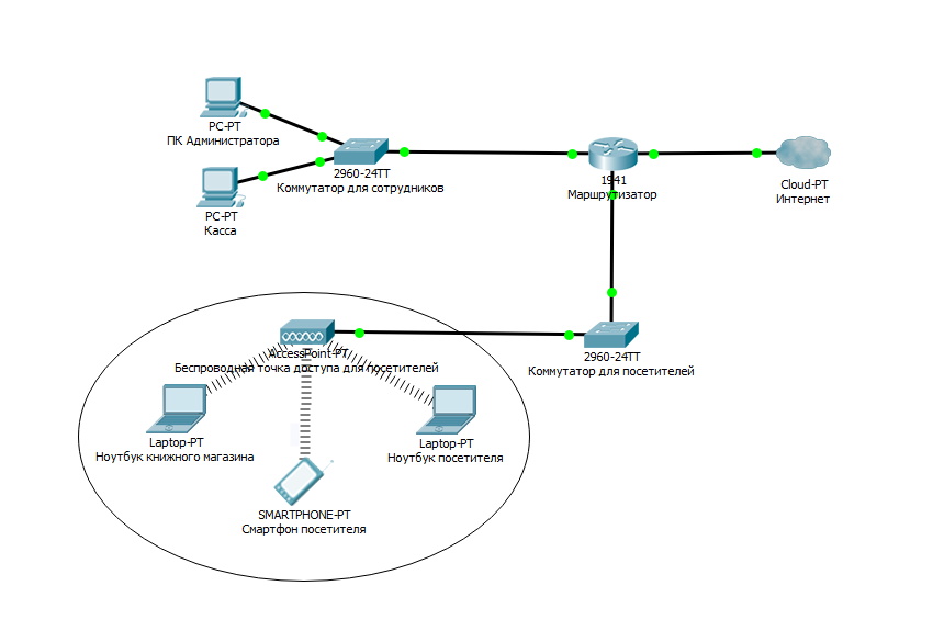
Портативные компьютеры посетителей взаимодействуют с устройством WLAN, называемым беспроводной точкой доступа (Access Point). Точка доступа использует радиоканал для отправки и получения фреймов (отдельных, законченных HTML-документов, которые вместе с другими HTML-документами могут быть отображены в окне браузера) от клиентского устройства, например, компьютера. Кроме того, точка доступа подключена к той же сети Ethernet, что и устройства, обеспечивающие работу магазина, следовательно, и покупатели, и сотрудники могут искать информацию на дистанционных веб-сайтах.
Сравнение беспроводных локальных сетей с локальными сетями
Беспроводные локальные сети во многом похожи с локальными сетями, например, оба типа сетей позволяют устройствам взаимодействовать между собой. Для обеих разновидностей сетей работает стандарт IEEE (IEEE 802.3 для сетей Ethernet и 802.11 — для беспроводных сетей). В обоих стандартах описан формат фреймов сети (заголовок и концевик), указано, что заголовок должен иметь длину 6 байтов и содержать МАС-адреса отправителя и получателя. Оба стандарта указывают, как именно устройства в сети должны определять, когда можно передавать фрейм в среду, а когда нельзя.
Основное отличие двух типов сетей состоит в том, что для передачи данных в беспроводных сетях используется технология излучения энергии (или технология излучения радиоволн), а в сетях Ethernet используется передача электрических импульсов по медному кабелю (или импульсов света в оптическом волокне). Для передачи радиоволн не нужна специальная среда работы, обычно говорят, что «связь происходит по воздуху», чтобы подчеркнуть, что никакой физической сети не надо. В действительности любые физические объекты на пути радиосигнала (стены, металлические конструкции и т.п.) являются препятствием, ухудшающим качество радиосигнала.
Стандарты беспроводных локальных сетей
IEEE определяет четыре основных стандарта WLAN 802.11: 802.11a, 802.11b, 802.11g и 802.11n.
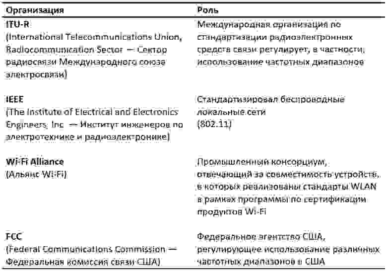
Наибольшее влияние на стандарты беспроводных сетей оказали следующие четыре организации (см. таблицу ниже)
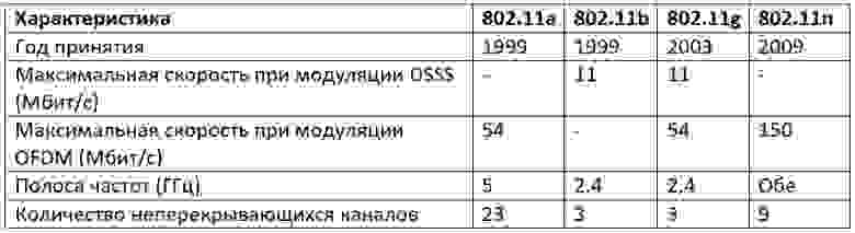
Сравнение стандартов WLAN
Термины
— DSSS (Direct sequence spread spectrum — Метод прямой последовательности для расширения спектра)
— OFDM (Orthogonal frequency-division multiplexing — мультиплексирование с ортогональным частотным разделением каналов)
Помимо основных стандартов из таблицы существуют дополнительные стандарты, которые указаны ниже.
Дополнительные стандарты
• 802.11 — изначальный 1 Мбит/с и 2 Мбит/c, 2,4 ГГц и ИК стандарт (1997).
• 802.11c — процедуры операций с мостами; включен в стандарт IEEE 802.1D (2001).
• 802.11d — интернациональные роуминговые расширения (2001).
• 802.11e — улучшения: QoS, пакетный режим (packet bursting) (2005).
• 802.11h — распределённый по спектру 802.11a (5 GHz) для совместимости в Европе (2004).
• 802.11i — улучшенная безопасность (2004).
• 802.11j — расширения для Японии (2004).
• 802.11k — улучшения измерения радиоресурсов.
• 802.11l — зарезервирован.
• 802.11m — поправки и исправления для всей группы стандартов 802.11.
• 802.11o — зарезервирован.
• 802.11p — WAVE — Wireless Access for the Vehicular Environment (беспроводной доступ для среды транспортного средства).
• 802.11q — зарезервирован, иногда его путают с 802.1Q.
• 802.11r — быстрый роуминг.
• 802.11s — ESS Wireless mesh network[en] (Extended Service Set — расширенный набор служб; Mesh Network — многосвязная сеть).
• 802.11u — взаимодействие с не-802 сетями (например, сотовыми).
• 802.11v — управление беспроводными сетями.
• 802.11w — Protected Management Frames (защищенные управляющие фреймы).
• 802.11x — зарезервирован и не будет использоваться. Не нужно путать со стандартом контроля доступа IEEE 802.1X.
• 802.11y — дополнительный стандарт связи, работающий на частотах 3,65-3,70 ГГц. Обеспечивает скорость до 54 Мбит/с на расстоянии до 5000 м на открытом пространстве.
• 802.11ac — новый стандарт IEEE. Скорость передачи данных — до 6,77 Гбит/с для устройств, имеющих 8 антенн. Утверждён в январе 2014 года.
• 802.11ad — новый стандарт с дополнительным диапазоном 60 ГГц (частота не требует лицензирования). Скорость передачи данных — до 7 Гбит/с
Также присутствуют две рекомендации. Буквы при них заглавные.
• 802.11F — Inter-Access Point Protocol (протокол обмена служебной информацией для передачи данных между точками доступа. Данный протокол является рекомендацией, которая описывает необязательное расширение IEEE 802.11, обеспечивающее беспроводную точку доступа для коммуникации между системами разных производителей).
• 802.11T — Wireless Performance Prediction (WPP, предсказание производительности беспроводного оборудования) — методы тестов и измерений (метод представляет собой набор методик, рекомендованных IEEE для тестирования сетей 802.11: способы измерений и обработки результатов, требования, предъявляемые к испытательному оборудованию).
Основные устройства и условные знаки в работе с Wi-Fi
1. Точка доступа – это беспроводной «удлинитель» проводной сети

2. Роутер – это более «умное» устройство, которое не просто принимает и передает данные, но и перераспределяет их согласно различным установленным правилам и выполняет заданные команды.

3. Облако – настроенная часть сети

4. Wi-Fi соединение
5. Прямая линия — кабель (витая пара)
Основные способы использования Wi-Fi
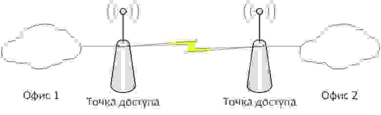
1. Wi-Fi мост – соединение двух точек доступа по Wi-Fi
2. Wi-Fi роутер – подключение всех устройств к роутеру по Wi-Fi (вся сеть подключена беспроводным способом).
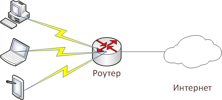
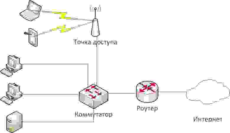
3. Wi-Fi точка доступа – подключение части сети для беспроводной работы
Задания лабораторной работы.
1. Создать и настроить второй и третий вариант использования Wi-Fi в Cisco Packet Tracer.
2. Настроить мост между двумя точками доступа (первый вариант использования Wi-Fi) на реальном оборудовании.
Выполнение лабораторной работы.
Задание №1 (вариант сети №2)
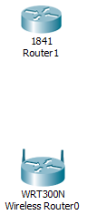
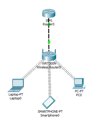
1. Создадим на рабочем поле Packet Tracer Wi-Fi маршрутизатор (он же Wi-Fi роутер)

2. Создадим маршрутизатор от провайдера (допустим, название провайдера – «Miry-Mir»). Я выбрал маршрутизатор Cisco 1841.
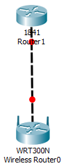
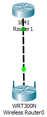
3. Соединяем их кросс-кабелем (пунктирная линия), так как устройства однотипные (роутеры). Соединяем так: один конец в Router1 в FastEthernet 0/0, а другой конец в Wireless Router0 в разъём Internet, так как Router1 раздаёт нам Интернет.
4. Настроим Интернет роутер (Router1) для работы с сетью. Для этого перейдём в настройки роутера дважды кликнув по нему и перейдём во вкладку CLI (Command Line Interface).
В диалоге «Would you like to enter the initial configuration dialog? [yes/no]:» (Вы хотите войти в начальное диалоговое окно конфигурации) пишем «no».
Пишем следующую последовательность команд:
Router>en

Router#conf t

Router(config)#int fa0/0

Router(config-if)#ip address 120.120.0.1 255.255.255.0

Router(config-if)#no shut

Router(config-if)#end

Router#wr mem
По традиции, рассмотрим их по порядку.
1) En – enable. Расширенный доступ к конфигурации
2) Conf t – Configuration terminal. Открывает терминал настройки
3) int fa0/0 – interface fastEthernet0/0. Переходим к настройки указанного порта (в нашем случае к fastEthernet0/0)
4) ip address 120.120.0.1 255.255.255.0 – задаётся IP адрес и его маска. Адрес – 120.120.0.1 (допустим, это адрес нам дал провайдер), маска – /24.
5) no shut – no shutdown. Включить, настроенный нами, интерфейс
6) End – завершения настройки.
7) wr mem – write memory. Сохранение конфигураций.
Соединение установлено.
5. Настроим беспроводной роутер (Wireless Router0) для работы с сетью. Для этого, как и в случае с предыдущим роутером, перейдём в настройки роутера дважды кликнув по нему. Во вкладках выберем графический интерфейс пользователя (GUI — graphical user interface). Такой режим будет отображён при вводе в любом браузере адреса роутера.
Выставим следующие настройки:
Internet Connection Type – Static IP

Internet IP Address – 120.120.0.2

Subnet Mask – 255.255.255.0

Default Gateway – 120.120.0.1

Router IP – 192.168.0.1

Subnet Mask (Router IP) – 255.255.255.0

Start IP Address – 192.168.0.100

Maximum numbers of Users – 50
И внизу страницы нажимаем кнопку «Save settings»
Разбор настроек:
Мы выбрали статический IP, так как провайдер выдал нам белый IP адрес (120.120.0.1/24). Путь по умолчанию (Default Gateway) – это адрес роутера от провайдера. Адрес роутера со стороны беспроводных устройств – 192.168.0.1/24. Роутер будет раздавать IP с 100 по 150.
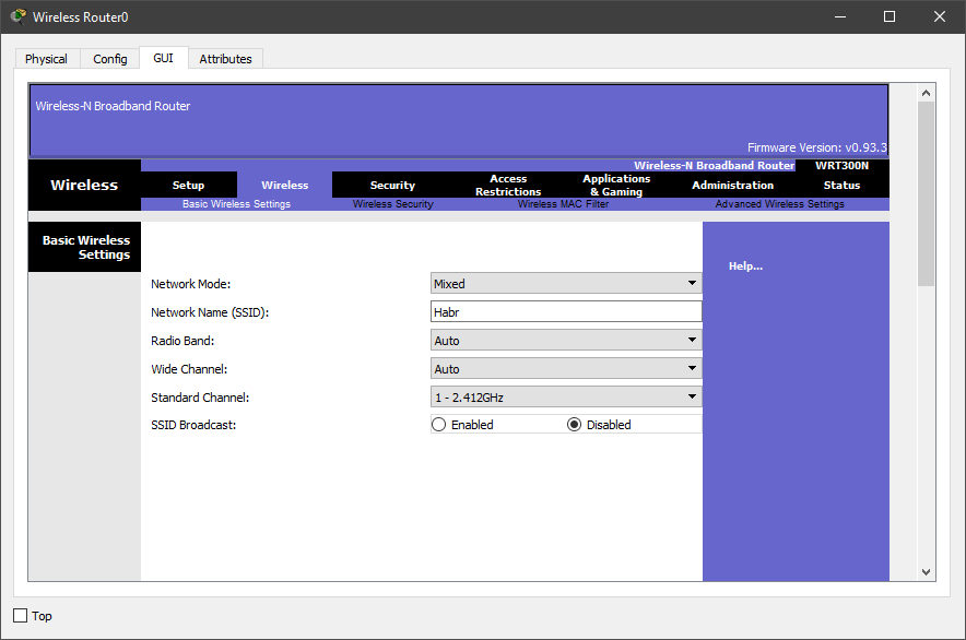
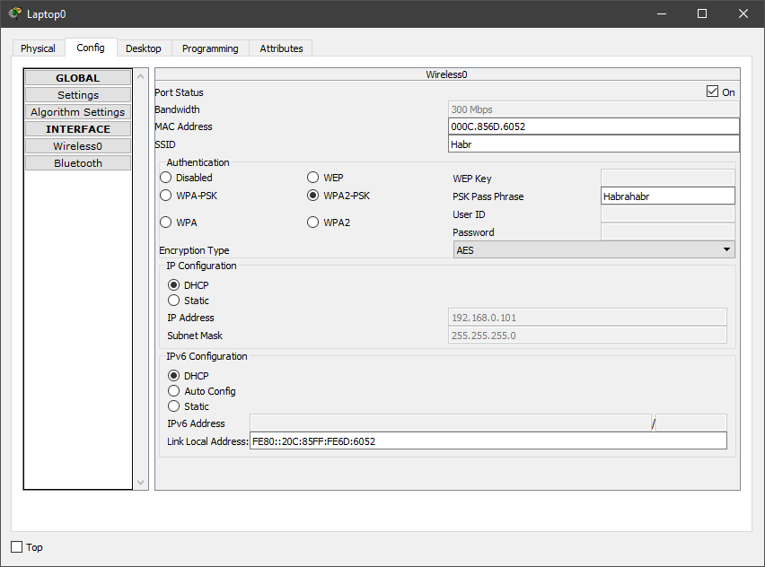
6. Переходим во вкладку Wireless, то есть беспроводное подключение.
Выставляем следующие настройки:
Network Mode – Mixed

Network Name (SSID) – Habr

Radio Band – Auto

Wide Channel – Auto

Standard Channel – 1 – 2.412GHz

SSID Broadcast – Disabled
И внизу страницы нажимаем кнопку «Save settings»
Разбор настроек:
Режим работы роутера мы выбрали смешанный, то есть к нему может подключиться любое устройство, поддерживающее типы роутера (в эмуляторе Cisco Packer Tracer – это g, b и n). Имя сети мы выставили Habr. Ширину канала роутер выберет сам (есть возможность выбрать либо 20, либо 40 мегагерц). Частота в эмуляторе доступна только 2,4GHz её и оставим. Имя сети мы скрыли, то есть устройства не увидят нашей сети Wi-Fi, пока не введут её название.
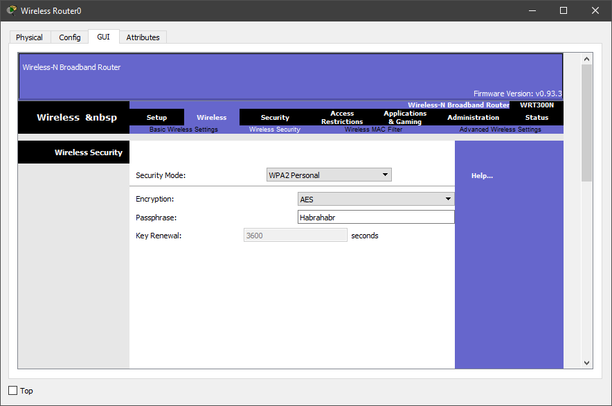
7. Настроим защиту нашего роутера. Для этого перейдём во вкладку Security и в пункте «Security Mode» выберем WPA2 Personal, так как WPA – уязвимая защита. Выбирать WPA2 Enterprise, тоже, не стоит, так как для ей работы нам потребуется радиус сервер, которым мы не занимались. Алгоритм шифрования оставляем AES и вводим кодовое слово. Я выставил Habrahabr.
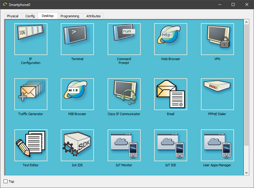
8. Добавим 3 устройства, как на схеме (смартфон, ноутбук и компьютер). Затем заменим разъёмы под rj-45 на Wi-Fi антенну (в смартфоне по умолчанию антенна).
9. Во вкладке Config выстави настройки, которые выставлялись на роутере. Данную операцию необходимо проделать на всех устройствах.
10. Переходим на рабочий стол любого компьютера и открываем командную строку.
11. Проверим какие адреса роутер выдал устройствам. Для этого введём команду ipconfig.
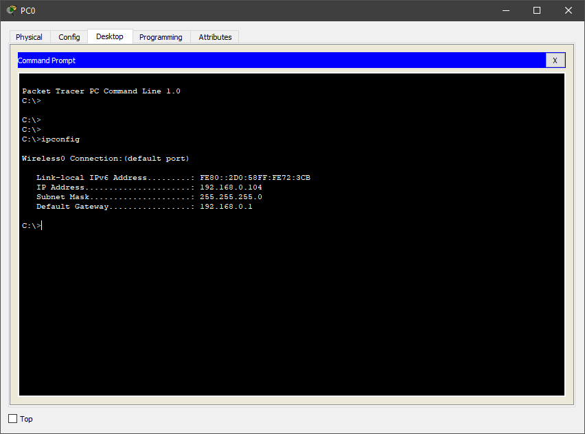
Как видно на скриншоте, роутер выдаёт адреса от 192.168.0.100 до 192.168.0.150.
12. Проверяем работоспособность сети из любого устройства командой ping. Пинговать будем 2 адреса – адрес роутера (192.168.0.1) и белый адрес (120.120.0.1), то есть проверим сможет ли устройство выйти в Интернет.

Снова, всё работает.
В итоге у нас получилась Wi-Fi сеть, которая изображена во втором варианте использования
Задание №1 (вариант сети №3)
1. Откроем готовый проект из предыдущей лабораторной работы по PAT.

2. Создадим точку доступа на рабочем поле программы и соединим её со свитчем. При желании точку доступа можно настроить (Port 0 – это физический порт, а Port 1 – беспроводной)
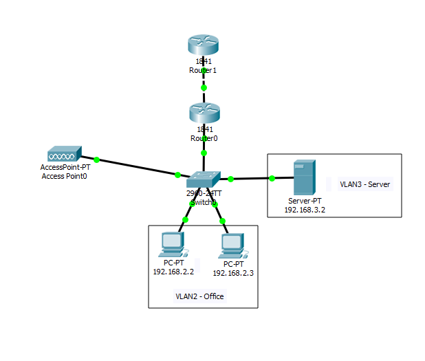
3. Создадим ещё один VLAN для беспроводной точки доступа.
4. Добавим в настройках роутера 0 VLAN 4, а также добавим его в access лист для выхода в интернет.
Так как это мы проделывали в предыдущих лабораторных работах (по VLAN и PAT), подробно останавливаться не буду, но пропишу все команды на устройствах
Свитч
Switch>en

Switch#conf t

Switch(config)#vlan 4

Switch(config-vlan)#name Wi-Fi

Switch(config-vlan)#exit

Switch(config)#interface FastEthernet0/5

Switch(config-if)#switchport access vlan 4
Роутер (сабинтерфейс)
Router>en

Router#conf t

Router(config)#int fa0/1.4

Router(config-subif)#encapsulation dot1Q 4

Router(config-subif)#ip address 192.168.4.1 255.255.255.0

Router(config-subif)#no shutdown

Router(config-subif)#end
Роутер (DHCP (Dynamic Host Configuration Protocol — протокол динамической настройки узла). Сетевой протокол, позволяющий компьютерам автоматически получать IP-адрес и другие параметры, необходимые для работы в сети TCP/IP)
Router#conf t

Router(config)#ip dhcp pool Wi-Fi-pool

Router(dhcp-config)#network 192.168.4.0 255.255.255.0

Router(dhcp-config)#default-router 192.168.4.1

Router(dhcp-config)#exit

Router(config)#ip dhcp excluded-address 192.168.4.1

Router(config)#end
Здесь остановлюсь поподробнее, так как ранее мы не встречались с данным параметром.
Router(config)#ip dhcp pool Wi-Fi-pool – создание пула (набора) dhcp адресов
Router(dhcp-config)#network 192.168.4.0 255.255.255.0 – сеть, в которой реализуется dhcp, и её маска
Router(dhcp-config)#default-router 192.168.4.1 – адрес по умолчанию (он же адрес роутера)
Router(config)#ip dhcp excluded-address 192.168.4.1 – исключение адреса роутера из раздачи по dhcp
Роутер (access лист)
Router(config)#ip access-list standard HABRAHABR

Router(config-std-nacl)#permit 192.168.4.0 0.0.0.255

Router(config-std-nacl)#exit

Router(config)#int fa0/1.4

Router(config-subif)#ip nat inside

Router(config-subif)#end
Добавим смартфон на рабочую область Packet Tracer и пропингуем ПК, сервер и Интернет, то есть 192.168.2.2, 192.168.3.2, 120.120.53.1.
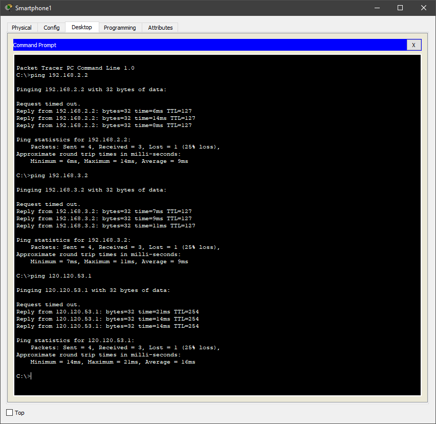
Как видно, всё работает.
Задание №2 (вариант сети №1)
К сожалению, в Packet Tracer нет возможности создать Wi-Fi мост (он же репитер или повторитель), но мы сделаем это простое действие на реальном оборудовании в графической среде.
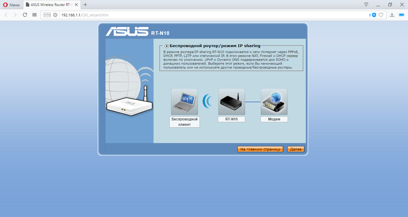
Оборудование, на котором будут проводиться настройки – роутер ASUS RT-N10 и, так называемый, репитер TP-LINK TL-WA850RE.
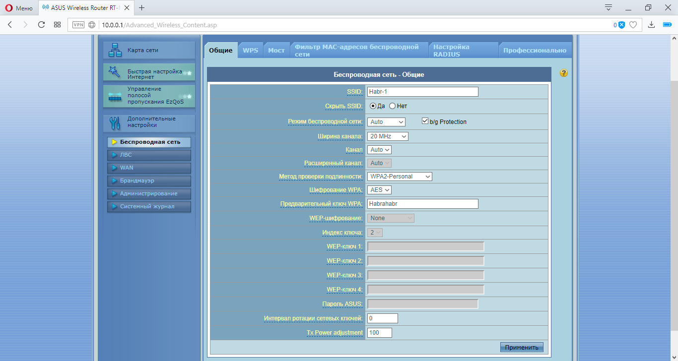
Перейдём к настройке роутера Asus. Для этого откроем браузер и введём адрес роутера (по умолчанию он сам откроется)
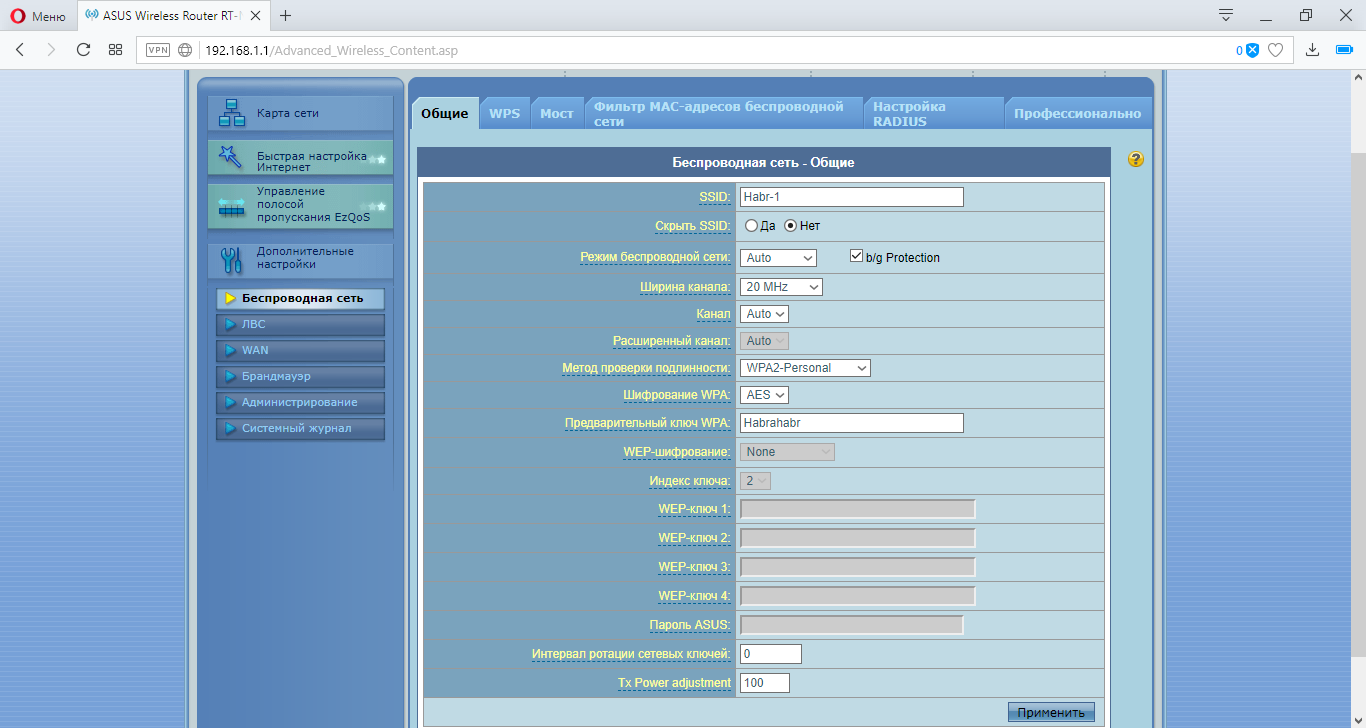
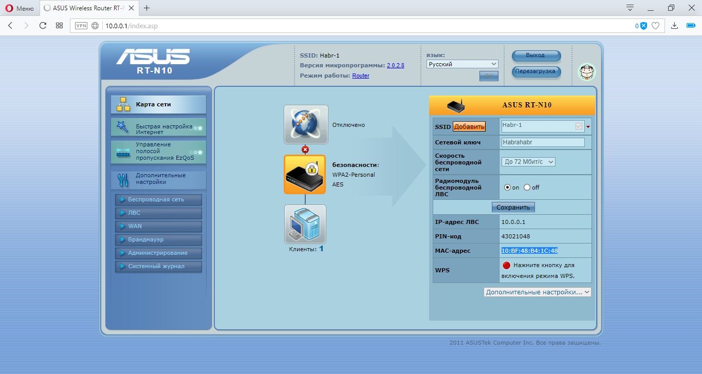
Переходим во вкладку «Беспроводная сеть» и выставим настройка как на скринжоте ниже.
Переходим во вкладку «ЛВС» (локальная вычислительная сеть) и выставляем следующие настройки.
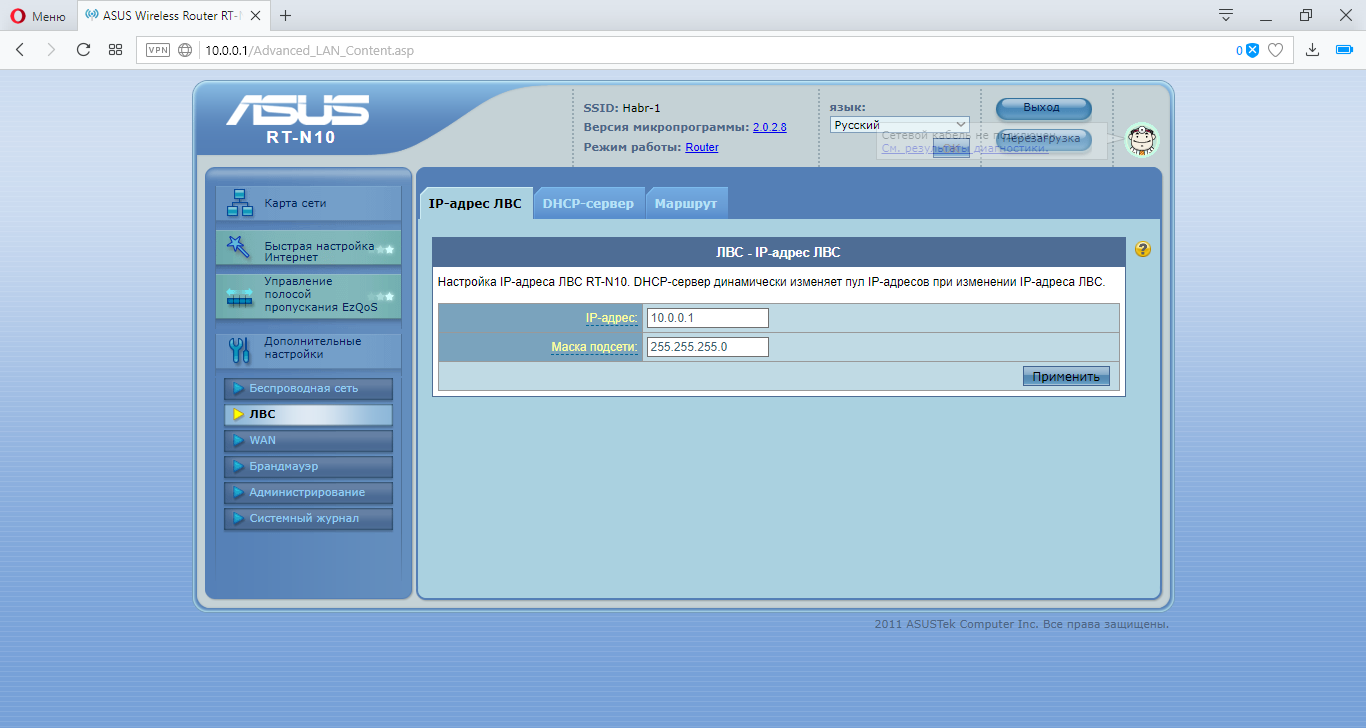
Переходим в главную вкладку. Там мы можем посмотреть наш MAC-адрес
Переходим к настройке репитора TP-LINK
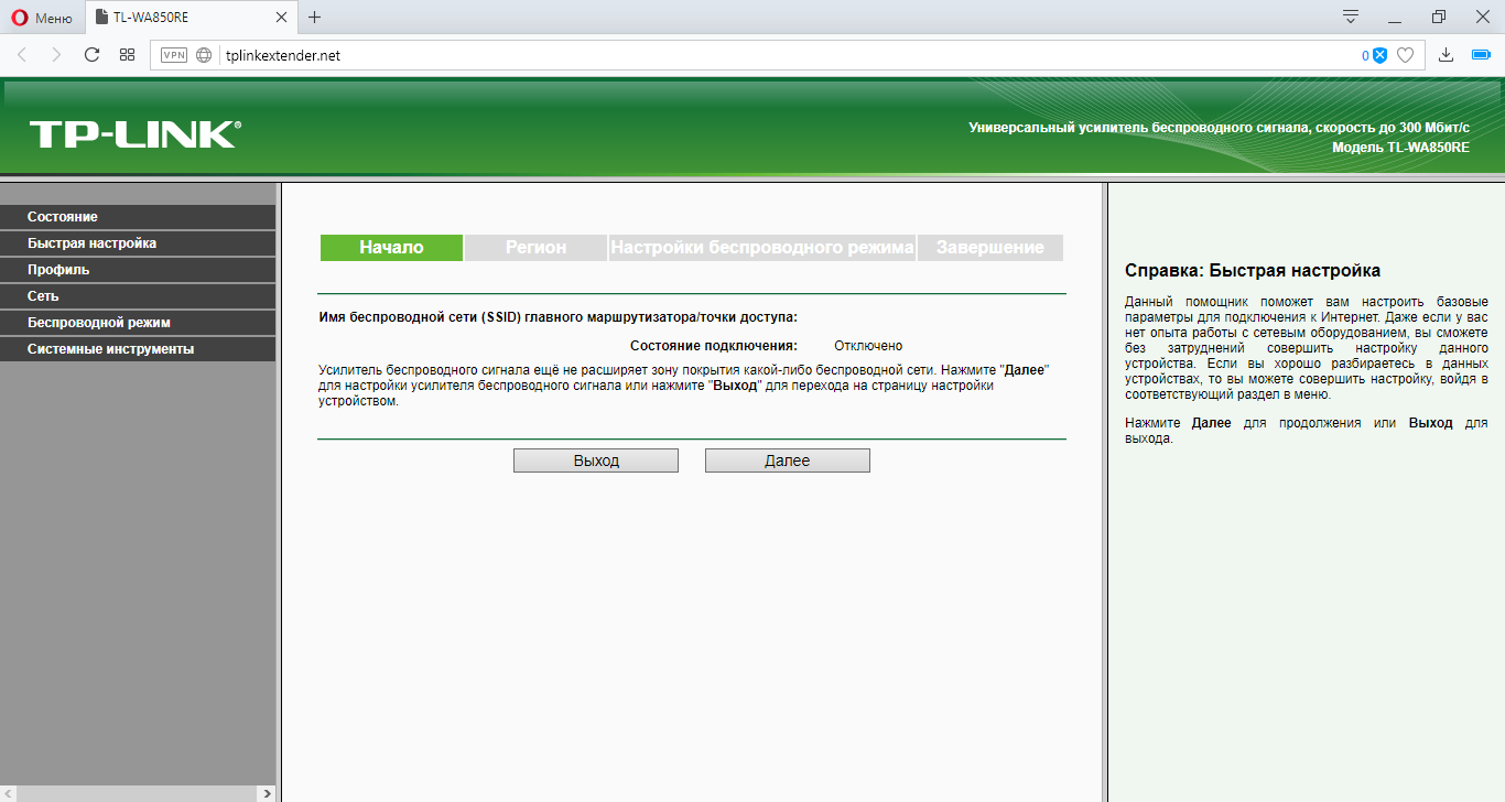
Нам автоматически устройство выдаст главное меню и режим быстрой настройки. Нажмём «Выход» и выполним настройку сами.
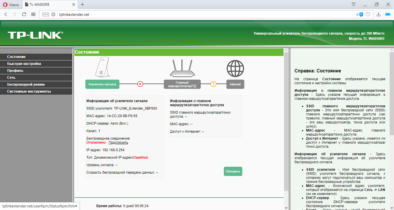
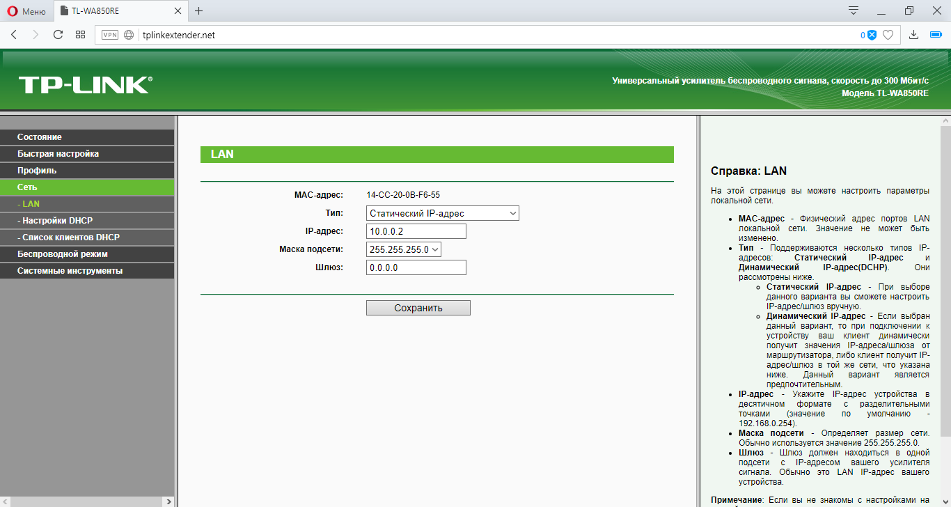
Переходим во вкладку «Сеть» и выставим следующие настройки.
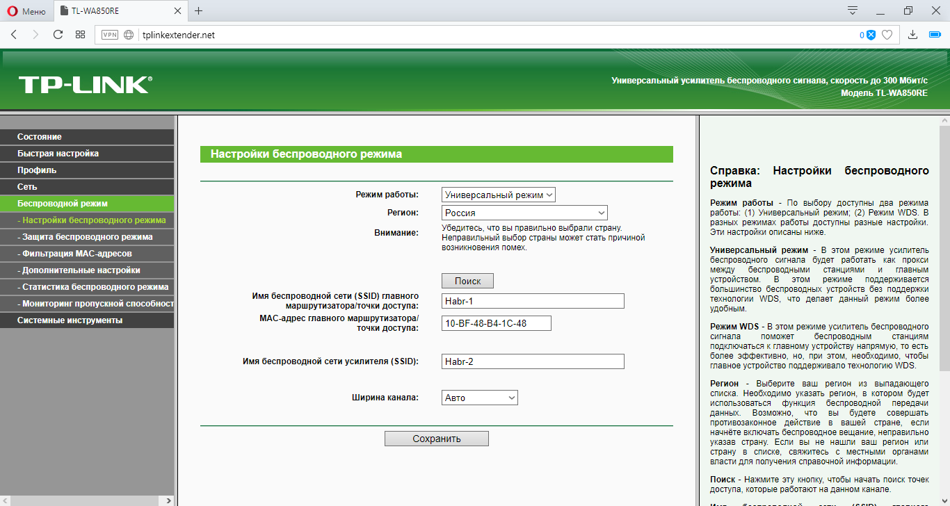
Переходим во вкладку «Беспроводной режим» и настраиваем входной и выходной поток.
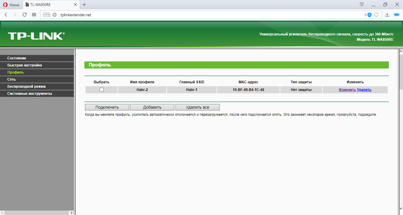
Во вкладке «Профиль» мы видим все созданные нами профили. Нажмём кнопку «Изменить»
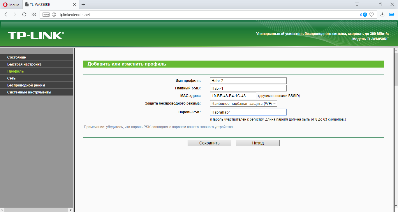
Настроим безопасность выходной сети добавлением ключа WPA2.
Переходим в главное меню и выбираем пункт «Подключить» в «Беспроводном соединении». Далее последует настройка моста. Возможно потребуется ввод пароля от роутера Asus.
После нажатия кнопки будет загрузка конфигураций
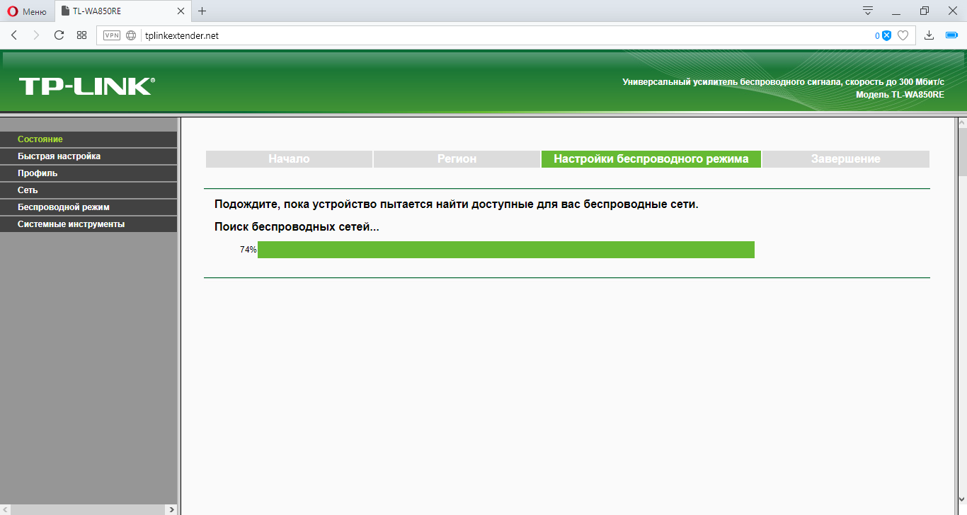
И вуаля! Всё готово!
Для того, чтобы не путаться к какому устройству подключаться, можно скрыть SSID на роутере Asus
Проверяем подключение по кабелю
Пинг успешен.
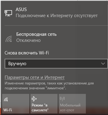
Проверка по Wi-Fi.
Успешно.
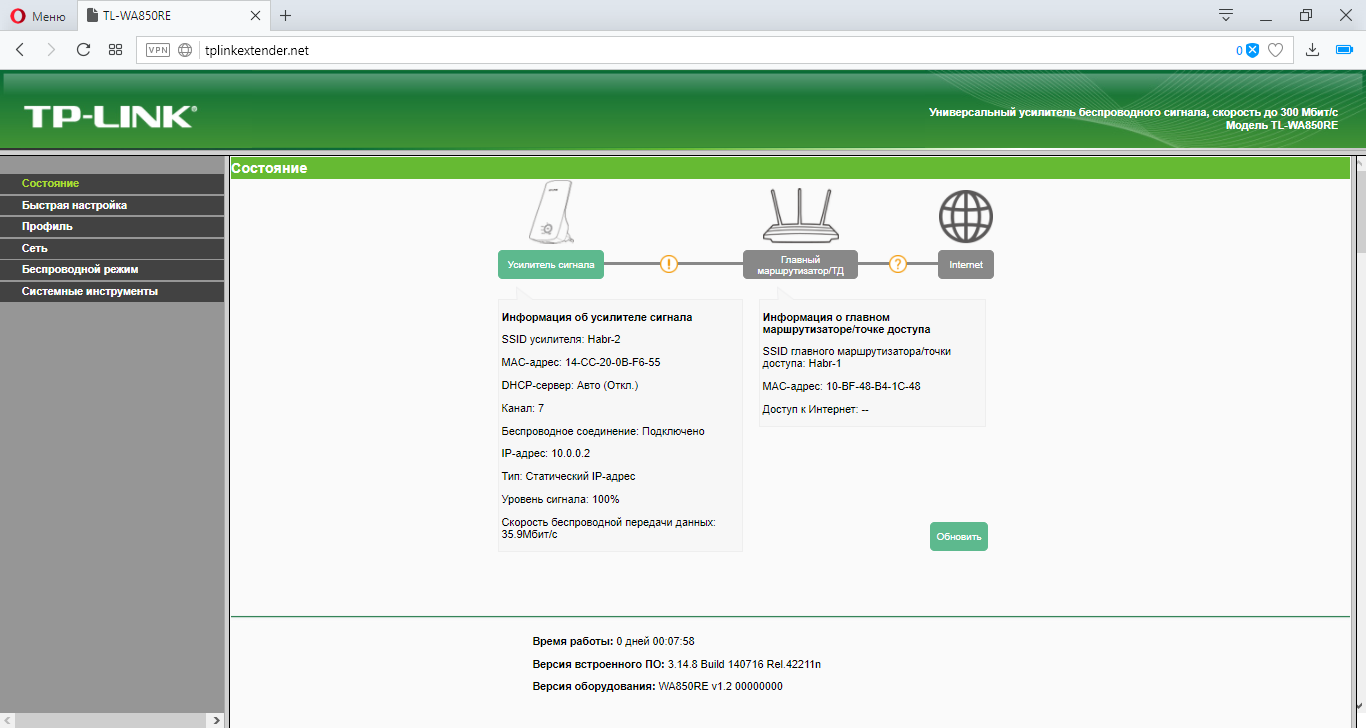
И просмотрим финальную конфигурацию, при подключении к ретранслятору.
Hello and welcome! This tutorial will give you an easy guide of configuring a wireless network in Packet Tracer using a wireless router. We’ll go through wireless LAN configuration, wireless security and configuring the wireless router for internet connectivity. Briefly, here are the configurations we’ll perform on the wireless router:
- Wireless LAN administration.
- Wireless LAN network setup.
- Securing a wireless network with WPA and WEP security features.
- Setting up internet connectivity on the wireless router.
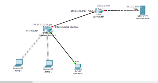
In our network set up, we have two laptops and a PC which should connect to a LAN provided by one wireless router.The PC is is used by the network Admin and connects to the LAN via an Ethernet port of wireless router.The laptops should connect to the same LAN by wireless means, and for this reason we’ll install wireless adapters on them. Still, we’ll need to connect the LAN to the internet via an ISP router.
Let’s now do all that step by step.
Wireless LAN configuration
First get into Cisco Packet Tracer and in the physical mode, pick a wireless router and two laptops,a PC, a generic server and a 2800-series router(or just any other router other than wireless).
Now connect the PC to the Ethernet 1 of the wireless router.
For the laptops, replace the already-installed wired LAN module with a wireless adapter module (WMP 300N) .
Make sure that you first power off each laptop before you make any replacement then restore the power back after replacement. That’s easy to do!
Once you have the wireless modules in place, you’ll see the wireless connections come up between the laptops and the wireless router as shown below.
Next, we’re going to do some settings on the wireless router to create a LAN then connect it to the internet.
To do any configuration on the wireless router, we’ll use its GUI(Graphical User Interface) which we can access either by:
- Clicking the Wireless Router icon then GUI tab, or
- Using a browser in a PC or laptop in the LAN.
Let’s use the PC to access the router GUI.
We’ll access the router from the PC or the laptops using the router’s LAN interface.The LAN interface is simply the default gateway of the LAN.
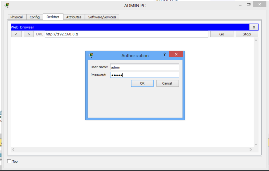
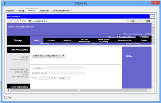
So now, on the ADMIN PC browser, type the IP address of the LAN interface of the wireless router.(192.168.0.1 by default ), then hit Go.
A login prompt appears. Provide the username (admin) and password (admin) to be allowed into the GUI of the router.You can always change these settings later.
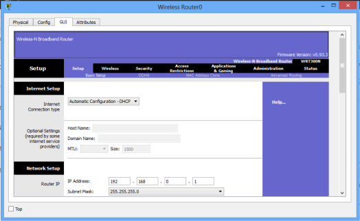
You should now be in the GUI of the router, whichever approach you chose to access it. Just examine it closely for a moment. On it, you can see several tabs like Setup, Wireless, Security, Access Restrictions, Application & Gaming, Administration and WRT 300N status.
For this tutorial we’ll focus on setup, wireless and administration tabs. Notice that once you click on one major tab, other ‘sub-tabs’ will appear.
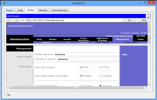
Wireless Router Administration
We’ll begin with Administration in the GUI. Here we’ll simply change the router’s username and password.
On the browser of Admin PC, type the IP address of the LAN interface of the wireless router(192.168.0.1, by default). Hit Go to access the GUI of the router. Provide the default username(admin) and password(admin). Click OK. You’re now on the GUI of the router. See it on the figure below.
Click on the Administration tab and set a new password for administrative access. Scroll down and Save settings. You will be prompted for a username and the new password you just set.Type them and click OK. Wait a bit. A new screen appears confirming settings are successful. You can click on continue to continue with configurations.
To test for the new password entered, close the browser of Admin PC and try to to access the GUI again using the browser. You’ll now provide the new password you’ve just set.
The admin username and password are important, as only a network admin(or a user with admin rights) is able to log into the router and manage its settings.
Let’s now move on to another setup.
LAN Setup and Internet Setup
To configure addresses for the LAN and internet connectivity, we’ll use Setup tab.
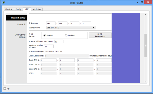
Network Setup
Network setup means LAN setup. Already, we have a PC and three laptops in the LAN.We’ll assign the them IP addresses either statically or dynamically (using a DHCP pool set up in the wireless router).
The default LAN network address given here is 192.168.0.0 with a subnet mask of 255.255.255.0 .The first address in this network (192.168.0.1 by default) has been assigned to the LAN interface of the router. It has just been named IP address. Obviously, all the PCs in the LAN will use the LAN interface as their default interface(to communicate to hosts in outside networks).
Now, in the router’s network settings, you may choose to enable DHCP to dynamically assign IP addresses to the PCs. On the other hand, if you choose to disable DHCP, then obviously, you’ll have to configure static IP addresses on the PCs.
When you choose to enable DHCP, set the start address for the LAN pool, maximum hosts to be allowed in your LAN and the DNS server for the LAN. The PCs will receive addresses automatically from the pool.
Now, going the DHCP way:
- Ensure DHCP is checked.
- Leave the IP address as 192.168.0.1 (This is the default LAN gateway address).
- Set a start address of 192.168.0.50 and set maximum users to 100 (or any number of users you want)
- You can leave the DNS server entry as it is (0.0.0.0) or specify the address of a DNS server of your choice.
- Scroll down and Save settings.
See the set up window below.
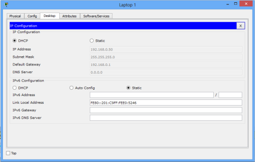
Moving on, let’s enable DHCP on each PC for dynamic configuration. Go to the IP configuration tab for each PC and enable DHCP. Each PC should automatically obtain an IP address from the router.
As an example, here is the IP configuration for Laptop1:
Now let’s test our wireless LAN.
Ping PC2 from PC1. Ping should succeed.
Try also to ping the LAN interface of the router from one of the PCs ,say, PC1 . It should be successful.
That was pretty easy! Let’s now move on and add wireless security for the wireless LAN access.
Adding security for wireless LAN access
The LAN network we have just setup has no wireless security features enabled. If this a was a production network, this would mean an obvious security threat since this makes the network accessible to unauthorized users. So let’s implement some level of wireless security to our LAN.
Access the GUI of wireless router (either by clicking on Router icon or from Admin PC browser), then click on Wireless tab. Under the Basic Wireless Settings sub tab, change the default wireless SSID to any name of your choice. I have named mine ‘myLAN‘. After this, don’t forget to Save settings.
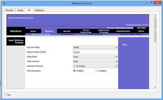
The acronym SSID stands for Service Set Identifier, and its the name of your wireless network(wireless LAN).
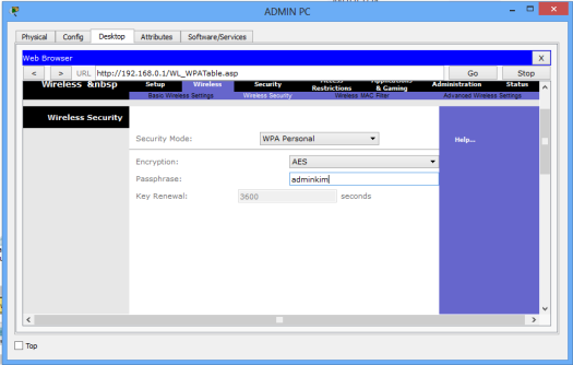
Still, in the Wireless tab, under the Wireless security sub tab, change security mode to WPA personal , then set passphrase field to a password of your choice. Scroll down and Save settings
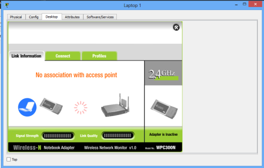
The LAN network is now secured for wireless access. To test whether its really protected, click Laptop1->Desktop->Wireless.
A new window appears that shows the now secured wireless network. Click connect. You can now see the name of the wireless network( myWIFI , in my case) and its signal strength. Site features listed include WPA1 PSK security feature.
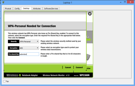
Again, click connect, then provide the security pre-shared key for the WiFi that you set, then connect. Laptop 1 is now connected to the WiFi network. You can see at the bottom right of the screen that the wireless network adapter on the laptop is active.Repeat this process for the Laptop2.
Now, you can change the wireless security mode to any other from the available options. You may choose WEP security feature for our wireless network, for example. For WEP, provide a 40-bit (10 hexadecimal digits e.g. A123B456C789) or 64 -bit key(16 hex characters). WEP and WPA configurations look almost alike.
That’s all for wireless security configuration.
Lastly, let’s see how to set up internet configurations on the wireless Router so that the PC and laptops in the LAN can access the internet. So move on to the next section.
Internet Setup
For this part, we’ll configure the internet interface on the router so as to connect our LAN to the internet. Note that for different routers (from different vendors), the internet interface may be named differently; in some routers, for example, the interface may have the name ‘WAN interface‘, suitably because its the interface that allows devices in our LAN to access the internet.
Here, we’ll connect the internet interface to an ISP router which then connects to an internet server (example.com, as an example).
So now, access the Internet Setup tab on the GUI of the wireless router (either by clicking on its icon or from admin PC browser). Actually, in a real life router configuration, you’ll use a PC browser. In this case you should remember the username name and the new password you set.
To Set internet connectivity , we’ll need to set a static IP address on the interface or set interface as a DHCP client so that it will be assigned an address dynamically by the ISP router. Alternatively, you may use PPPoE to provide WAN connectivity to the internet.
Now, if you choose to configure a static IP address for the internet interface, you can specify also the default gateway and a DNS server of your choice.
And, if you’d rather like to have the internet interface address configured by DHCP, you’ll then set the internet interface as a DHCP client. A DHCP server will be configured on another device, such as the ISP router (in our topology here!).
Otherwise, if you choose PPPoE for internet connectivity, then set up the username and password for PPPoE authentication. The internet interface will then become a PPPoE client and will negotiate for connection with a PPPoE server running on an ISP device so as to achieve internet connectivity.Usually the username and password will be provided by your ISP.
For now, we’ll set the internet interface to act as a DHCP client (with the DHCP server configured on the ISP router)
So then :
First configure IP addresses and a DHCP server on ISP router.
ISP_ROUTER(config)#int fa0/0
ISP_ROUTER(config-if)#ip add 155.21.21.1 255.255.0.0
ISP_ROUTER(config-if)#no shut
ISP_ROUTER(config-if)#
ISP_ROUTER(config-if)#int fa0/1
ISP_ROUTER(config-if)#ip add 200.0.0.1 255.255.255.0
ISP_ROUTER(config-if)#no shut

ISP_ROUTER(config-if)#exit

ISP_ROUTER(config)#ip dhcp pool mypool
ISP_ROUTER(dhcp-config)#net 155.21.0.0 255.255.0.0
ISP_ROUTER(dhcp-config)#default-router 155.21.21.1
ISP_ROUTER(dhcp-config)#dns-server 0.0.0.0
Now make the internet interface a DHCP client by enabling DHCP on it.
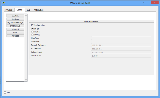
To verify DHCP configuration,click on the wireless router icon, then go to Config tab. Pick DHCP. The interface is now configured with an IP address from the pool set in the ISP router.
Next,we have to configure static or dynamic routes in the ISP router for the devices in the wireless LAN to gain access the internet server:
Here is a static route:
ISP_ROUTER(config)#ip route 192.168.0.0
                    255.255.255.0 fa0/0
Lastly, assign an IP address to the internet server (if you hadn’t done so), then try to reach the server from a host in the LAN.
For example, you can ping the server from Laptop1. Ping should succeed.
That’s all for this tutorial, and I hope you found the tutorial helpful. I also strongly believe that if you’ve gotten everything presented in here,then you have more than a foundation to create your own wireless network using a wireless router, e.g, home WiFi. It’s my believe!
Cheers!
See also:
- How to configure DHCP server in Packet Tracer.
- Configuring DHCPv6 (both stateless and stateful) in Packet Tracer.
- DNS server configuration in Packet Tracer
- IP helper-address configuration in Packet Tracer
In this lab, we will configure WIFI in Cisco packet tracer and we will be enabling the laptop for wireless connection using a wireless router
Download
Configuring a wireless router and creating a wireless network is easy in a packet tracer. It is almost the same as configuring the home wireless router.
There are varieties of wireless devices given in the packet tracer so we will select the wireless router WRT300N from the list.
Now, we have to configure the wireless router. Most of the settings are already configured on the wireless router required to establish a wireless network however, we can change the configuration as per our requirement and enable features like an access list, MAC address filtering, firewall, etc.
We can change the DHCP scope as per our requirements however in this lab but we will keep those settings to default.
SSID is configured as ‘default’ but we will change that to ‘packet’ and wireless security is disabled by default on the router so we will enable security and set up a password.
WPA2personal security mode has been selected and password packet123 has been configured on the router.
After configuring the router, we must save the setting. The save button is not visible on the screen until we scroll down.
Now, we will configure the laptops so they can join the wireless network.
By default, the laptop does not have a WPC300N module installed and there is no extra space to install the module so we have to remove the Ethernet module and replace it with a WPC300N module.
Before changing the module, the laptop must be powered off otherwise, the module cannot be changed.
If we will not change any setting on the router then changes are not required on the laptop as well because the laptop is preconfigured with the SSID and a password is not required so the laptop will establish the connection with the router just by installing the wireless module.
As we have changed the SSID and password on the router, we should configure the laptop with the required information.
The laptop will establish a connection when configured with the appropriate SSID and password. Now, we can open the GUI of the wireless router on the web browser of the laptop.
We have to enter the IP address of the server in the web browser and then the browser will ask for the username and password, which is admin for both. After the successful authentication, we will be able to configure the router on a laptop.

To configure a WiFi router in packet tracer (Cisco) you need to follow the following three steps:
- Configure the wireless router
- Configure the Wireless client
- Verify if you are connected.
On configuring the wireless client, you need to follow the following steps:
Step 1: Connect the Internet interface of WRS2 to S1.
Step 2: Configure the Internet connection type. WSR2>GUI tab
Step 3: Configure the network setup. IP 172.17.40.1 and subnet is 255.255.255.0 then enable DHCP server
Step 4: Configure wireless access and security. Network mode should be wireless-N only.
For Configuring the Wireless client:
Step 1: Configure PC3 for wireless connectivity. …
Step 2: Verify PC3 wireless connectivity and IP addressing configuration.
What is Packet Tracer?
Packet Tracer is a Cisco network design simulation software. It allows for hands-on tutorials, which can be completed within an hour. This software also allows you to assign tasks and collaborate with other classmates or virtual users.
Packet Tracer is a Cisco network design and simulation software used by network engineers and students. Packet Tracer software is based on the latest Cisco IOS Software technology and helps you learn networking basics through realistic simulations.
Packet tracer is a software that will give you an idea of how things work and how to configure the different devices. Packet Tracer can be downloaded for free from the Cisco website and is compatible with Windows 10, 8.1, 8, 7, Vista, and XP.
To get started with it you just need to open the program and drag some cables between routers or nodes. You could also enter commands in order to create a scenario like adding authentication between two routers/nodes.
Packet tracer is great if you are trying to learn something new or want to walk yourself through configuring equipment.
Packet Tracer is a software that will allow you to create and configure networks. This software has the capability to simulate real-world scenarios like an internet connection or a VoIP call. In order to use Packet Tracer, you will have to have a Cisco network device.
Step 1: Open Packet Tracer and then open the Devices tab on the left side of the screen.
Step 2: Add your device by clicking on “Add Device.” Then, select your type of device from the drop down menu and click “Add.”
Step 3: Configure your router by going to Edit > Configuration > Basic Setup.
Step 4: Select Wireless Network Connection Type as WLAN, enter SSID for name, just for fun feel free to change Security Mode as WPA2-PSK (AES) and select a password for it.
How to configure wireless client in Packet Tracer?

To configure a wireless client in Packet Tracer, follow the following three steps:
1. Configure the wireless router
2. Configure the Wireless client
3. Verify if you are connected.
On configuring the wireless client, you need to follow the following steps:
Step 1: Connect the Internet interface of WRS2 to S1.
Step 2: Configure the Internet connection type. WSR2>GUI tab
Step 3: Configure the network setup. IP 172.17.40.1 and subnet is 255.255.255.0 then enable DHCP server
Step 4: Configure wireless access and security. Network mode should be wireless-N only
Configure the wireless router

First, you need to configure the wireless router. You can do this by entering into the wireless router interface and configuring the SSID, security mode, and other details.
1. Configure the wireless router by typing “config t” in the command prompt
2. Type “no ip domain-lookup”
3. Type “ip domain-name mydomain.com”
4. Type “ip address dhcp”
5. Type “no shutdown”
Related: How to Update Router’s Firmware: Easy step-by-step guide
Configure the Wireless client
On configuring the wireless client, you need to follow the following steps:
Step 1: Connect the Internet interface of WRS2 to S1.
Step 2: Configure the Internet connection type. WSR2>GUI tab
Step 3: Configure the network setup. IP 172.17.40.1 and subnet is 255.255.255.0 then enable DHCP server
Step 4: Configure wireless access and security. Network mode should be wireless-N only
Verify if you are connected
To verify if you are connected, go to the “show ip interface brief” command verify that the IP address is in the same subnet as the wireless router.
Step 1: Ping PC3 from WRS2.
Step 2: Ping PC3 from WSR1.
Step 3: Ping PC3 from PC2.
How do I configure my Cisco wireless router?
This article will give you step-by-step instructions on how to configure your wireless router.
Step 1: Connect PC1 to the LAN port on WRS1.
Step 2: Enter the IP address 192.168.1.2 into the computer’s browser window and press enter.
Step 3: Under “Wireless Settings,” select “Enable Wireless.”
Step 4: Click on “Wireless Mode” and choose “N Only (802.11n)” from the drop down menu.
Step 5: Click on “Wireless Network Name” and enter a desired Network Name (SSID). Put numbers in front of your desired name, for example “MyWiFiNetwork.”
Step 6: Click on “Security Mode” and choose WPA/WPA2 Personal from the drop down menu.
Step 7: Click on “Passphrase.” Enter a password, which should be at least 8 characters long with different types of characters such as letters, numbers and symbols like !@#$%^&*. Click OK when finished entering the password then click Next. >
How do I find my wireless router in Packet Tracer?
In packet tracer you can locate the wireless router by following these steps:
- Open the command line
- Type “sh management”
- You will see a list of devices on your network and select your wireless router.
To find your wireless router in Packet Tracer, you will need to follow these steps:
1. Click on Network -> Laptop -> Wireless
2. Verify the connection of Client PC1 with the wireless router
3. Verify that the name of the wireless router is “WRS2”
4. Set your IP address to “172.17.40.1” – this is a cheap option if you have a wired connection
5. Configure DHCP server and enable it by clicking “Enabled”
How to connect laptop to wireless router in packet tracer
To connect laptop to wireless router in packet tracer (Cisco) you need to follow the following two steps:
1. Configure an Ethernet connection
2. Verify if you are connected.
On configuring Ethernet connection, you need to follow the following steps:
Step 1: Connect PC3 to S1 with a crossover cable
Step 2: Configure PC3 for Ethernet connectivity. IP 172.17.40.2 and subnet is 255.255.255.0 then enable DHCP server
On verifying if you are connected, you need to follow the following steps:
Step 1: Ping 192.168.1.254
How to configure access point in packet tracer
To configure an access point in a packet tracer (Cisco) you need to follow the following four steps:
1. Connect the internet interface of R1 to S1
2. Configure the Internet connection type
3. Configure network setup
4. Configure wireless access and security
What is the router configuration in cisco packet tracer?
The router configuration in packet tracer is to configure your wireless router and wireless clients.
1. Configure the wireless router:
– Go to the “configuration” tab and choose “wireless.”
– Choose a frequency band and channel width (11a/g/n) then click “Apply.”
– Click on “Wireless Clients” tab then choose a SSID and password then click “Apply.”
– Choose a security mode (WEP, WPA, or WPA2) then click “Apply.”
2. Configure the Wireless client:
– Connect the Internet interface of the PC to S1.
– Configure an IP address, subnet mask, default gateway, and DNS server.
– Enable DHCP server on network setup page.
– Select network mode as wireless-N only.
Conclusion
Configuring a wireless router in Packet tracer (Cisco) is easy and you will get to the desired result.
To find your wireless router in Packet Tracer, you need to follow these steps:
- Open a Packet Tracer session
- Type “sho ip int brief”
- Look for the number of the interface that has an IP address. This is usually your wireless router.
Packet Tracer is a software that is used to create and test packets in order to improve the understanding of networking concepts. Packet Tracer is a virtualized lab environment for developing, testing, and demonstrating network configuration.
Packet Tracer is also used for teaching Cisco courses.
In conclusion, in order to configure wifi router in packet tracer you need to follow the three steps. The first step is configuring the wireless router on which you will have to set up the IP address, subnet and DHCP server.
Next, you need to configure the wireless client. In order to do this, you will have to connect the internet interface of WRS2 with S1 and then configure the IP address. Once that’s done, you need to configure wireless connection type by specifying Network mode as wireless-N only. Finally, verify if your PC3 is connected with an IP address.
FAQs
To configure WRS2 wireless router in a packet tracer (Cisco), what is the first step?
Configure the wireless router. To do it click on the “Configure Wireless” link and then click on “Wireless Security”.
What type of security should I use?
Use WPA2-PSK.
What is the general configuration for a wireless router?
Configure the interface with an IP address and subnet, set a DHCP server to assign IP addresses, configure wireless access and security.
What are the steps in configuring PC3 for wireless connectivity?
Configure PC3 to be able to connect wirelessly; verify that PC3 is connected.
What is Packet Tracer?
Packet Tracer is a network and security software that allows you to learn about networking. Packet Tracer is a simulator for Cisco networks containing exact copies of the software and commands used in today’s Cisco hardware.